Having finally got my boiler (Biomass 60) installed and attached to a chimney I'm trying to figure out how to do the hard part (plumbing ")
I'm planning to build a 800g or so unpressurized tank with a copper coil heat exchanger for storage. Pressurized might be simpler but lack of a suitable tank and physical constraints with getting it next to the boiler make it difficult.
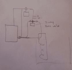
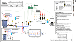
What I'm finding hard is coming up with a simple way to manage the boiler and storage. The attached diagram (with apologies for the literal cutting and pasting) shows what I have come up with so far. This is really no more than a primary/secondary system with a 4 way mixing valve. Here is how I think/hope it might work.
When the boiler is cold the secondary loop will be off and the 4 way valve will be held in the 'neutral' position allowing the (short) primary loop to circulate directly as the boiler warms up. Once the boiler inlet has reached a good temperature, the 4 way valve will be moved towards the position shown to force circulation into the HX and add heat to the tank. How far it goes can be controlled based on boiler inlet temperature to make sure this doesn't fall below its set point. If the secondary loop calls for heat that is less than the currently available output from the boiler the 4 way valve will move back towards neutral to accommodate. If the secondary loop calls for heat that exceeds the currently available output from the boiler the 4 way value will return to neutral and the mixing valve on the secondary loop will reduce the heat taken from the primary loop to hold up boiler inlet temperature.
As the boiler starts to go out, the 4 way valve will move towards the opposite direction to that shown reversing the flow in the HX and providing heat to the primary loop from storage. Initially this can be used to top up whatever heat is still being produced by the boiler based on the load on the secondary loop. When the boiler finally goes out the 4 way valve will move fully to the opposite direction and all heat to the primary loop will come from storage. Although its not shown on the diagram I would add a 3 way diversion valve to bypass the boiler from the primary loop once the boiler is out.
Well that's the theory. I'm a total newbie at this though. Think it will work in practice? Any and all comments gratefully received.
Cheers,
Simon.
I'm planning to build a 800g or so unpressurized tank with a copper coil heat exchanger for storage. Pressurized might be simpler but lack of a suitable tank and physical constraints with getting it next to the boiler make it difficult.
What I'm finding hard is coming up with a simple way to manage the boiler and storage. The attached diagram (with apologies for the literal cutting and pasting) shows what I have come up with so far. This is really no more than a primary/secondary system with a 4 way mixing valve. Here is how I think/hope it might work.
When the boiler is cold the secondary loop will be off and the 4 way valve will be held in the 'neutral' position allowing the (short) primary loop to circulate directly as the boiler warms up. Once the boiler inlet has reached a good temperature, the 4 way valve will be moved towards the position shown to force circulation into the HX and add heat to the tank. How far it goes can be controlled based on boiler inlet temperature to make sure this doesn't fall below its set point. If the secondary loop calls for heat that is less than the currently available output from the boiler the 4 way valve will move back towards neutral to accommodate. If the secondary loop calls for heat that exceeds the currently available output from the boiler the 4 way value will return to neutral and the mixing valve on the secondary loop will reduce the heat taken from the primary loop to hold up boiler inlet temperature.
As the boiler starts to go out, the 4 way valve will move towards the opposite direction to that shown reversing the flow in the HX and providing heat to the primary loop from storage. Initially this can be used to top up whatever heat is still being produced by the boiler based on the load on the secondary loop. When the boiler finally goes out the 4 way valve will move fully to the opposite direction and all heat to the primary loop will come from storage. Although its not shown on the diagram I would add a 3 way diversion valve to bypass the boiler from the primary loop once the boiler is out.
Well that's the theory. I'm a total newbie at this though. Think it will work in practice? Any and all comments gratefully received.
Cheers,
Simon.