
I'm adding a Flex Fuel 30kw. I have a 2650 sqrt colonial with 1400 sqrt basement. I currently have 4 zones. I'm refinishing the basement adding it as my fifth zone. I currently have zone valves. A couple have stopped working and were replaced. I'll upload pictures of my current oil setup tonight. Trying to see what would be the best and most practical way to plumb the zones. I know there's not one ultimate solution. I'm also aware pumps require more watts, so I'm lost at this point. I'm open to
Zone Valves, Pumps or Both
- Thread starter Pologuy9906
- Start date
-
Active since 1995, Hearth.com is THE place on the internet for free information and advice about wood stoves, pellet stoves and other energy saving equipment.
We strive to provide opinions, articles, discussions and history related to Hearth Products and in a more general sense, energy issues.
We promote the EFFICIENT, RESPONSIBLE, CLEAN and SAFE use of all fuels, whether renewable or fossil.
You are using an out of date browser. It may not display this or other websites correctly.
You should upgrade or use an alternative browser.
You should upgrade or use an alternative browser.
- Status
- Not open for further replies.
Even if you were to have a pump for each zone I'd still put a zone valve in there to prevent ghost flow. I have two zones and each zone has a pump and a valve. My brother started without zone valves (a pump on each zone) and installed zone valves after a only short period.


alaskawild
New Member
Pologuy
Taco loves to ask the question you are posing now! What should I us on zones, circs or zone valves? The answer is either will work! Some like circs and some like zone valves. I've done them both ways over the years. Living here in Fairbanks has sort of pushed me toward zone valves with one circ. The reason behind this thinking is that if the pump takes a dump you can put almost any pump that might be at hand in as a replacement to keep the system running even if it may not be the ideal size. Emergencies require emergency action at times here. If a zone valve fails they can be manually opened to restore circulation. You then have time to obtain the correct parts. Ideally home owners would keep spares on hand but this is not the norm sadly! LOL.
I've gone almost exclusively to Taco delta t pumps for this type of setup. You could of course go with the Grundfos Alpha delta p version. I've just started leaning toward Taco because of a wide range of sizes in their delta t line. Of course if you want to go the ECM route, sizing becomes a little more of an issue if you have high head numbers.
I personally would never install both individual circs and zone valves. Cost being the number one issue. If you have thermal syphoning issues there are better ways to address this. Of course if you go the route I described you don't need to worry about "ghost heat".
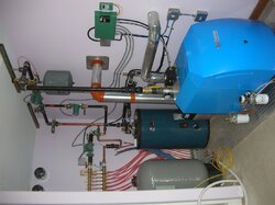
Looking at your pic if you are going to do some rework I have a few suggestions. Take them for what there worth. You should always if possible pump away from your boiler. In other words the pump should be located on the supply side of the boiler. Ideally your air scoop would have at least 18 inches of straight pipe before entering the scoop. It takes this much room for the majority of air bubbles that are traveling in the water column to rise to the upper part of the pipe to allow the scoop to work most efficiently. Remember that air does not carry btu's so it is costing you to continue to send them around the loop. Water and no air is key.
Your circ should go into the system right after the air scoop. If you do it this way you will have the ideal zero pressure differential area. This is what you want when at all possible. Of course all of this info just refers to your existing system.
Good Luck!
Taco loves to ask the question you are posing now! What should I us on zones, circs or zone valves? The answer is either will work! Some like circs and some like zone valves. I've done them both ways over the years. Living here in Fairbanks has sort of pushed me toward zone valves with one circ. The reason behind this thinking is that if the pump takes a dump you can put almost any pump that might be at hand in as a replacement to keep the system running even if it may not be the ideal size. Emergencies require emergency action at times here. If a zone valve fails they can be manually opened to restore circulation. You then have time to obtain the correct parts. Ideally home owners would keep spares on hand but this is not the norm sadly! LOL.
I've gone almost exclusively to Taco delta t pumps for this type of setup. You could of course go with the Grundfos Alpha delta p version. I've just started leaning toward Taco because of a wide range of sizes in their delta t line. Of course if you want to go the ECM route, sizing becomes a little more of an issue if you have high head numbers.
I personally would never install both individual circs and zone valves. Cost being the number one issue. If you have thermal syphoning issues there are better ways to address this. Of course if you go the route I described you don't need to worry about "ghost heat".
Looking at your pic if you are going to do some rework I have a few suggestions. Take them for what there worth. You should always if possible pump away from your boiler. In other words the pump should be located on the supply side of the boiler. Ideally your air scoop would have at least 18 inches of straight pipe before entering the scoop. It takes this much room for the majority of air bubbles that are traveling in the water column to rise to the upper part of the pipe to allow the scoop to work most efficiently. Remember that air does not carry btu's so it is costing you to continue to send them around the loop. Water and no air is key.
Your circ should go into the system right after the air scoop. If you do it this way you will have the ideal zero pressure differential area. This is what you want when at all possible. Of course all of this info just refers to your existing system.
Good Luck!
I would agree that going with both is unnecessary. You can chalk what I did up to two things; availability and inexperience. The pumps were nice self contained units that included the thermostat controllers. They were available at Menards. They still allowed a little thermal siphoning though, so I threw the zone valves in to stop that. I also didn't really realize there were multiple zone controllers that took care of everything. I would do that if I had to redo it, but I would still have valves in because my boiler is in the basement and there was definite flow.
Bob Rohr
Minister of Fire
Another option is to leave the pump on the return, and the air scoop where it is , but move the expansion tank connection down to the suction side of the circ. Tee it into the boiler feed line as the fill valve should be at the PONPC, which is the expansion tank connection. Might be less re-work, and it will correct two issues.
Also it looks like that boiler may have been condensing a bit based on the floor stains and condition of that flue pipe? It needs to be up above 140F at the return within 10- 15 minutes of start up. or maybe it is short cycling too much under low load conditions?
Might be wise to add a return protection thermostatic valve if you are doing re-piping.
Skip the ZV with pumps, use the internal check provided with the pump, and a second spring check on the return side if you have ghost flow concerns.

alaskawild
New Member


Bob Rohr
Minister of Fire
No shortage of joint compound there ")
When you use teflon tape, be sure to start two threads back. If you go to, or over the end you will end up with "shards" inside the piping. It gets into circ pump impellers, zone valves, all sorts of places you don't want it.
When you use teflon tape, be sure to start two threads back. If you go to, or over the end you will end up with "shards" inside the piping. It gets into circ pump impellers, zone valves, all sorts of places you don't want it.
Attachments
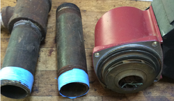
I'll wipe that all off today. Overall does it appear the components and piping are where they need to be?
Flex Fuel coming this week. Need to wrap this up tonight.
Flex Fuel coming this week. Need to wrap this up tonight.
Bob Rohr
Minister of Fire
Close! If that pump is pushing flow into the return side of the boiler, I'd move the expansion tank and fill valve there. You have enough fittings to do it, just move them around.
Install the ball valve on the nipple coming up from the boiler return, put the pump flange above that. On the other side of the circ (suction side) put that reducing tee to connect the expansion tank and fill valve.
Or move the pump up to the air purger, pumping away from it.
The pump really needs to pump away from the expansion tank connection, so that the pressure differential it creates adds to the static fill pressure.
It's nice to have a valve on both sides of the pump to service or repair without a drain down.
Attachments
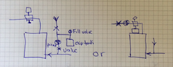
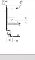
What's on the top in the drawing to the left? With the special Riello burner for the direct vent kit, and the field control vent kit, will I attach a flex hose from the burner air intake to the side of the combustion air tee?
www.fieldcontrols.com/.../46483500.pdf
www.fieldcontrols.com/.../46483500.pdf
alaskawild
New Member
Your air scoop should have at least 18" of smooth pipe, no fittings before it enters the scoop. That is if you use an air scoop such as the one shown. I see this issue all the time. I second Bob's comments. I personally like the pump on the supply (boiler discharge) side. You need that expansion tank and scoop in the zero pressure differential area.
alaskawild
New Member

alaskawild
New Member
Ok pologuy...
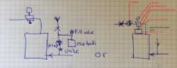
I marked up Bob's diagram with the way I would do it (see attached). Your auto fill would connect into a tee just below the air trap. I would place ball valves on the tee to isolate the auto fill and expansion tank if needed at a later date. If you find you are limited for space installing the expansion tank, you can mount it remotely to a wall near by and connect it from there with 1/2" oxygen barrier PEX. PEX is just easier to route. You could also use ridged pipe. If space is not an issue hang it directly from the tee, Also when I mention the tee, that does not mean that nipples to achieve you connection are not acceptable. You can use nipples to make everything fit if needed. Also I keep mentioning the 18" rule. This only applies to air scoop devises like you show. Again if space is an issue there are other devises out there that allow you to mount immediately after a fitting. The air scoop you have works great but you need to give it that 18" for best results.
I marked up Bob's diagram with the way I would do it (see attached). Your auto fill would connect into a tee just below the air trap. I would place ball valves on the tee to isolate the auto fill and expansion tank if needed at a later date. If you find you are limited for space installing the expansion tank, you can mount it remotely to a wall near by and connect it from there with 1/2" oxygen barrier PEX. PEX is just easier to route. You could also use ridged pipe. If space is not an issue hang it directly from the tee, Also when I mention the tee, that does not mean that nipples to achieve you connection are not acceptable. You can use nipples to make everything fit if needed. Also I keep mentioning the 18" rule. This only applies to air scoop devises like you show. Again if space is an issue there are other devises out there that allow you to mount immediately after a fitting. The air scoop you have works great but you need to give it that 18" for best results.
Attachments
alaskawild
New Member
pologuy...
Sorry I couldn't open your fieldcontrols PDF. From what little I can see of the boiler I believe it's a Buderus115. Is that correct? You mentioned a Riello burner. If that's correct make sure it's the correct model. You also mentioned direct vent. Not sure if you have this manual but checkout the Buderus 115 direct vent info below. Verify correct burner and oil primary control. I typically do not use any type of flex hose. Always rigid for me. Specs are in install info attachment.
Sorry I couldn't open your fieldcontrols PDF. From what little I can see of the boiler I believe it's a Buderus115. Is that correct? You mentioned a Riello burner. If that's correct make sure it's the correct model. You also mentioned direct vent. Not sure if you have this manual but checkout the Buderus 115 direct vent info below. Verify correct burner and oil primary control. I typically do not use any type of flex hose. Always rigid for me. Specs are in install info attachment.
alaskawild
New Member
I looked at the new schematic. So nothing on the return side? Just go from the return from the house straight to the boiler? Where would I put the return protection thermostatic valve? You also mention space issues and not necessarily need to use the air scoop. What would I use?
alaskawild
New Member
Pologuy...
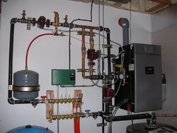
No, use your air scoop! I was just giving ideas if you can't get the 18" requirement or you had trouble getting your expansion tank in. You currently have an air scoop. They are very simple in design and work very well if installed correctly. If you can't get the 18" free flow pipe space then you should us an air separator. I'm attaching a pic of one (Spirotherm) from one of my installs for a customer. It also shows what I was telling you about mounting an expansion tank remotely. If you have the room attach the exp tank directly to air scoop. I'm also attaching a Danfoss TV manual that shows how to mount a TV. I highlighted the models you should look at. I also made a note on the document. Scroll down until you see a yellow notation bubble. Click on that and it will open to view note. Hope that helps.
No, use your air scoop! I was just giving ideas if you can't get the 18" requirement or you had trouble getting your expansion tank in. You currently have an air scoop. They are very simple in design and work very well if installed correctly. If you can't get the 18" free flow pipe space then you should us an air separator. I'm attaching a pic of one (Spirotherm) from one of my installs for a customer. It also shows what I was telling you about mounting an expansion tank remotely. If you have the room attach the exp tank directly to air scoop. I'm also attaching a Danfoss TV manual that shows how to mount a TV. I highlighted the models you should look at. I also made a note on the document. Scroll down until you see a yellow notation bubble. Click on that and it will open to view note. Hope that helps.
Last edited:
alaskawild
New Member
Thanks so much you guys simplified this dramatically. I took all the advice given. I took EVERYTHING apart and cleaned it. I reworked some of the return pipes to add ball valves between important components. I had the clearance. What I'll do with the exp tank is come from the air scoop with a nipple to ball valve to a nipple to a street 90 about a foot away then the exp tank.
I have a new concern. When I pipe in the flex fuel the pump on the return side is above the heat transfer plate. How would I do that? Coming off the back of the boiler it comes out and when it goes up I left a tee with a plug. Just in case I decide to add anything later.
I have a new concern. When I pipe in the flex fuel the pump on the return side is above the heat transfer plate. How would I do that? Coming off the back of the boiler it comes out and when it goes up I left a tee with a plug. Just in case I decide to add anything later.
Attachments
alaskawild
New Member
Lol. Where does the danfoss tv go? Based on the Flex Fuel schematic, how do you suggest I add in the heat plate transfer? It appears the transfer plate cuts the the return line. I attached another picture


- Status
- Not open for further replies.
Similar threads
- Replies
- 36
- Views
- 5K
- Replies
- 11
- Views
- 2K
- Replies
- 19
- Views
- 4K
- Replies
- 24
- Views
- 3K