I'm really enjoying reading the accumulated experience on this forum; thanks to all for sharing.
This is something I wrote earlier, mainly for solar heat systems.
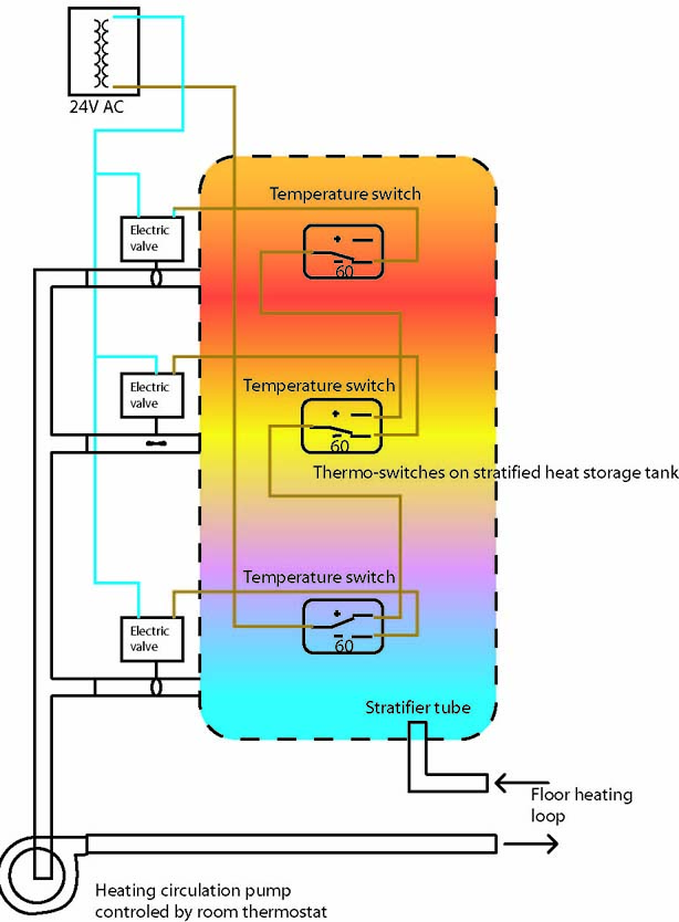
However, it is also relevant for biomass and other heat sources; mainly, it would be good to use the statification tube for the return end of your heating loops, to keep the tank as stratified as possible. The point of that is so you're more likely to have very hot water at the top of your storage tank for your DHW. Also, as the tank cools, you can still extract some useful energy from the top even when most of the tank has become too cool.
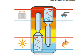
The stratification tube is what introduces heat into the tank. Here's the clever part; the incoming hot water should be directed into the tank at the level where the temperature is the same as the incoming water. Cold water is removed from the bottom to be heated, and the warm layer slowly moves down. Hot water will be at the top of the tank, and be used mostly for Domestic Hot Water [dhw]. The middle of the tank, at 40°-60° will be used for home heating.
When you get strong sun, 80°-90° water will be produced, and sent to the top of the tank.
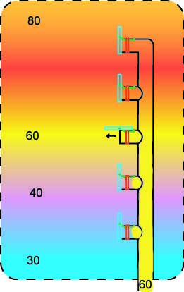
Let's say your solar collector output is at 60C. It will rise past the lower flaps, since the higher density cooler water on the other side holds them closed. It will not rise into the hotter water above, since the entering 60° water is denser and heavier than it. It will push open the flap at the point in the tank where there is the least resistance, which is at the point of equal density and temperature.
The water in the tube above the open valve will heat up through the tube walls.
The flaps should open with not more than a couple of grams of pressure, and fall closed by gravity. They don't need to seal perfectly, as at the ultra low pressure difference against them, little water will leak through. The important thing is that they don't stick, and move freely, even after years in the water. It will be hard to tell if something isn't working right, and even harder to fix.
The tank should have an access door for maintenance.
The artwork is mine, but the principle of operation is well known and proven.
This system works best with a glycol mixture, as glycol changes density with temperature more than plain water does; but for a big tank like this, glycol is too expensive. Therefore, make the tank as tall as possible, preferably 3 meters [10 feet]. The extra height equals extra stratification.
The stratification tube;
After a lot of searching, and even consulting with university professors of solar energy, I found this design. It seems to be the only one known to work consistently, but it's not possible to buy it as an individual part. It's patented by Solvis and they only sell it as part of their storage tanks. Therefore, this information is for educational purposes only!
The concept; very sensitive and large format check valves will simply let water into the heat storage tank at more or less the level where water of the same temperature and density is.
Colder, denser water in the bottom of the storage tank will hold the lower valve closed. warmer, lighter water will float above.
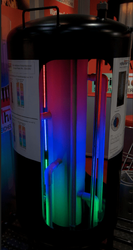
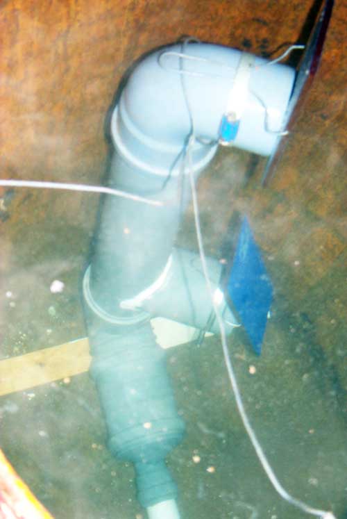
To test the principle of this, I built a simple test rig from a steel oil barrel and some plumbing parts. I let water out of the tank from the bottom while introducing new water in through my trial stratification tube.
This is to simulate what would be happening if it were connected to a solar collector.
This is my experimental version, not meant for actual use; the construction of this one isn't robust enough to work for 10 or 20 years in hot water. The pipe is 90mm [4"] PVC drain tube and the flaps are made from "trespa", a material similar to Formica but 6mm [1/4"] thick. It's waterproof and heavier than water.
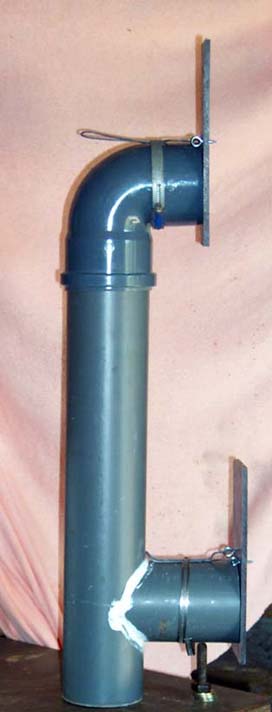
The first try, in the first photo, didn't work well. Although hot water did exit the top while sucking the bottom closed, the valve only opened an inch or so. the water squeezing through the gap entered the tank at too high a velocity. This is known to cause turbulence, mixing, and loss of stratification.
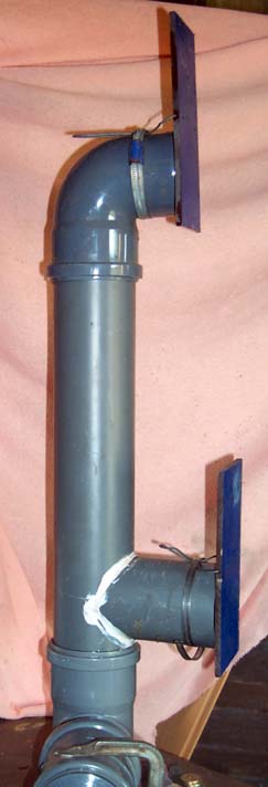
In the second photo I've made a slight change; the pivot points are drilled into the center of the valve body, instead of using rings behind it. This made for a better balance.
The flap was weighted to have only 2 grams more weight below the pivot than above [when under water]. This worked perfectly.
In this photo, I'm letting 55C water into the 90mm stratifier tube at about 40 liters per minute. the top flap is fully open, water velocity is low. The lower flap, which was hanging slightly open before the flow was started, is now pulled closed, presumably by the venturi effect.
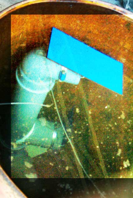
In this photo, I'm letting 18C water into the tank. the layer of hot water floats above as the cold water enters at the bottom, right where we want it.
I used an infrared thermometer to monitor the water temperature through the thin steel barrel. The temperature difference was clearly measurable, although there was a "fade" zone instead of the desired sharp thermocline. I suspect this was a combination of imprecise measuring technique [the steel barrel would conduct some heat from the hot to the cold area] and mixing due to the small size of my test barrel in relation to the large stratifier tube size.
The density of plain water changes only slightly as the temperature rises, so to use the effect the valves have to be very sensitive. A glycol solution would have about twice the effect, but I intend to build a tank in the region of 5 tons, and I don't want to buy 2,500 liters of glycol. And if I did, I would need another 5 ton tank to pump it into in case I needed to modify or work on the heat tank.
With water I can just dump it and pump in new.
It's important that the fluid velocity be low enough to prevent turbulence and mixing, which will cause a loss of stratification.
According to published research, outlet velocity should not be more than 0.15 meters per second. In other words, a very gentle but steady flow.
For 40mm tubing [38mm ID]; 0.192 lps [liters per second] or 11.52 lpm or 691 lph
60mm tubing [56mm ID]; 0.414 lps or 24.8 lpm or 1490 lph
80mm tubing [74mm ID]; 0.547 lps or 32.82 lpm or 1969 lph
The choice of tube diameter will depend on your fluid flow, which is determined by the size of the circulation pump and your solar collector array.
But as a rule of thumb, bigger is better.
This is something I wrote earlier, mainly for solar heat systems.
However, it is also relevant for biomass and other heat sources; mainly, it would be good to use the statification tube for the return end of your heating loops, to keep the tank as stratified as possible. The point of that is so you're more likely to have very hot water at the top of your storage tank for your DHW. Also, as the tank cools, you can still extract some useful energy from the top even when most of the tank has become too cool.
The stratification tube is what introduces heat into the tank. Here's the clever part; the incoming hot water should be directed into the tank at the level where the temperature is the same as the incoming water. Cold water is removed from the bottom to be heated, and the warm layer slowly moves down. Hot water will be at the top of the tank, and be used mostly for Domestic Hot Water [dhw]. The middle of the tank, at 40°-60° will be used for home heating.
When you get strong sun, 80°-90° water will be produced, and sent to the top of the tank.
Let's say your solar collector output is at 60C. It will rise past the lower flaps, since the higher density cooler water on the other side holds them closed. It will not rise into the hotter water above, since the entering 60° water is denser and heavier than it. It will push open the flap at the point in the tank where there is the least resistance, which is at the point of equal density and temperature.
The water in the tube above the open valve will heat up through the tube walls.
The flaps should open with not more than a couple of grams of pressure, and fall closed by gravity. They don't need to seal perfectly, as at the ultra low pressure difference against them, little water will leak through. The important thing is that they don't stick, and move freely, even after years in the water. It will be hard to tell if something isn't working right, and even harder to fix.
The tank should have an access door for maintenance.
The artwork is mine, but the principle of operation is well known and proven.
This system works best with a glycol mixture, as glycol changes density with temperature more than plain water does; but for a big tank like this, glycol is too expensive. Therefore, make the tank as tall as possible, preferably 3 meters [10 feet]. The extra height equals extra stratification.
The stratification tube;
After a lot of searching, and even consulting with university professors of solar energy, I found this design. It seems to be the only one known to work consistently, but it's not possible to buy it as an individual part. It's patented by Solvis and they only sell it as part of their storage tanks. Therefore, this information is for educational purposes only!
The concept; very sensitive and large format check valves will simply let water into the heat storage tank at more or less the level where water of the same temperature and density is.
Colder, denser water in the bottom of the storage tank will hold the lower valve closed. warmer, lighter water will float above.
To test the principle of this, I built a simple test rig from a steel oil barrel and some plumbing parts. I let water out of the tank from the bottom while introducing new water in through my trial stratification tube.
This is to simulate what would be happening if it were connected to a solar collector.
This is my experimental version, not meant for actual use; the construction of this one isn't robust enough to work for 10 or 20 years in hot water. The pipe is 90mm [4"] PVC drain tube and the flaps are made from "trespa", a material similar to Formica but 6mm [1/4"] thick. It's waterproof and heavier than water.
The first try, in the first photo, didn't work well. Although hot water did exit the top while sucking the bottom closed, the valve only opened an inch or so. the water squeezing through the gap entered the tank at too high a velocity. This is known to cause turbulence, mixing, and loss of stratification.
In the second photo I've made a slight change; the pivot points are drilled into the center of the valve body, instead of using rings behind it. This made for a better balance.
The flap was weighted to have only 2 grams more weight below the pivot than above [when under water]. This worked perfectly.
In this photo, I'm letting 55C water into the 90mm stratifier tube at about 40 liters per minute. the top flap is fully open, water velocity is low. The lower flap, which was hanging slightly open before the flow was started, is now pulled closed, presumably by the venturi effect.
In this photo, I'm letting 18C water into the tank. the layer of hot water floats above as the cold water enters at the bottom, right where we want it.
I used an infrared thermometer to monitor the water temperature through the thin steel barrel. The temperature difference was clearly measurable, although there was a "fade" zone instead of the desired sharp thermocline. I suspect this was a combination of imprecise measuring technique [the steel barrel would conduct some heat from the hot to the cold area] and mixing due to the small size of my test barrel in relation to the large stratifier tube size.
The density of plain water changes only slightly as the temperature rises, so to use the effect the valves have to be very sensitive. A glycol solution would have about twice the effect, but I intend to build a tank in the region of 5 tons, and I don't want to buy 2,500 liters of glycol. And if I did, I would need another 5 ton tank to pump it into in case I needed to modify or work on the heat tank.
With water I can just dump it and pump in new.
It's important that the fluid velocity be low enough to prevent turbulence and mixing, which will cause a loss of stratification.
According to published research, outlet velocity should not be more than 0.15 meters per second. In other words, a very gentle but steady flow.
For 40mm tubing [38mm ID]; 0.192 lps [liters per second] or 11.52 lpm or 691 lph
60mm tubing [56mm ID]; 0.414 lps or 24.8 lpm or 1490 lph
80mm tubing [74mm ID]; 0.547 lps or 32.82 lpm or 1969 lph
The choice of tube diameter will depend on your fluid flow, which is determined by the size of the circulation pump and your solar collector array.
But as a rule of thumb, bigger is better.