My progress in building a wood fired boiler based on the design by Richard C. Hill

  • Active since 1995, Hearth.com is THE place on the internet for free information and advice about wood stoves, pellet stoves and other energy saving equipment.

    We strive to provide opinions, articles, discussions and history related to Hearth Products and in a more general sense, energy issues.

    We promote the EFFICIENT, RESPONSIBLE, CLEAN and SAFE use of all fuels, whether renewable or fossil.
Status
Not open for further replies.
During the summer months down under I have been busy rebuilding the primary and secondary chambers of my wood boiler and have some pictures to display.

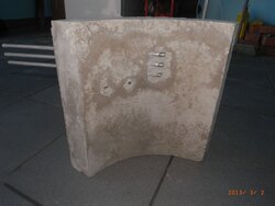
The burn chamber was caste in five parts using high temperature refractory and the pieces were butted together and held firmly in place inside a steel drum and surrounded by refractory insulation.

A tube leads to the new secondary chamber which has a steel outer casing and is lined with firebricks and refractory insulation. A clean-out port is installed in the top of the secondary chamber.

The outlet from the secondary chamber feeds heated air to the heat exchanger.

The blue drum on top of the wood feed chamber is to contain flames that may leap out when dropping wood into the chamber. (This does not happen if the air supply fan is switched off)

The flow of cold water into the heat exchanger is controlled by the motorized 2 inch ball valve and a thermostat.

Air is fed into the burn chambers by fourteen stainless steel tubes in a manner to cause swirling and great turbulence.

I am now waiting for some cold weather to give the heater a test run with the new components installed.


The heater with text.jpgSide wall.jpgBurn chamber exit.jpgBurn chamber being assembled.jpgSecondary chamber.jpgEnd of secondary chamber.jpgAsh clean out port.jpgFeed Chamber 2.jpgMotorized 2 inch  ball valve.jpg
 

Attachments

  • Side wall.jpg
    Side wall.jpg
    114.6 KB · Views: 493
Wow, you've really done a lot of work there; it looks great.
I'd like to know more about the refractory lining; did you make those sections yourself? The fit looks really impressive. I would think the segmented combustion chamber will be able to expand and contract a bit as necessary without cracking.
 
Hi Mark,

I made the sections myself. I had as friend in an engineering business roll pieces of steel for the inner and outer faces of each mold. The sides and bottom of the molds were cut from plywood. As I filled the molds with refractory cement I vibrated them by placing them on top of the running four stroke motor of my high pressure cleaner. (All high tech!) The cast pieces were kept damp for a couple of days and then allowed to dry naturally for a week. I then baked them in my kitchen oven for about eight hours. (I tried to get them fired professionally but I couldn't find anyone who was game to take on the task)

I made the burn chamber in pieces for ease of handling and because a monolithic structure would most likely crack as you have pointed out. I put a lot more effort into making the burn and secondary chambers than I did initially and I am hoping for a longer service life.
 
  • Like
Reactions: BoilerMan and ScotO
Did you use refractory needles?

I've used an old vibrating palm sander on top of concrete molds with success in the past.
 
Excellent work.

I doubt you will have problems with the refractory cast in sections as you have done, but I feel compelled to offer a word of caution.
This winter all three of the boilers at my workplace decommissioned themselves after having the firebox burn through at a joint in similarly cast refractory. The flame had burned through 3/8" plate steel after seeping through a joint in the refractory! The boilers are 16 years old.

I feel a tongue and groove section or mating lip cast into the edge of each piece may have prevented this erosion.
You are certainly dealing with far less power - these boilers are rated at 150 hp - and it may not be a problem at all, but I do encourage you to keep the joints as close as possible and watch for any signs of erosion.
 
Thanks for the responses.

I didn't use refractory needles as I read a number of opinions online that needles would not extend the life of the refractory.

I applied furnace cement to the joins during assembly and packed high temperature refractory insulation behind each joint with a two inch overlap. (I will keep my fingers crossed)
 
Hi Hobartian,

Great job as usual. Was your original construction becoming really decrepit or is this new work mainly your perfectionism in action?

I have still not started on mine. Got too busy with paid work overseas. However I have just posted a thread with my ideas, if you are interested.
https://www.hearth.com/talk/threads/concept-for-diy-furnace.109736/

You can see I am really trying hard to make the heat exchanger easier to build. Related to that, how ofter have you found cleaning the fire tubes in your boiler is really necessary?

Peter
 
Hi Snail,

The new work was unavoidable as the original clay pots lined with refractory materials crumbled into a multitude of pieces. The new design has everything contained within steel casings which should help to hold things together.

The addition of the control valve to feed the storage water into the heat exchanger is designed to avoid water contained in the flu gases condensing in the heat exchanger when the water in the storage tank is relatively cool.

In regard to cleaning the fire tubes: In the original design my secondary chamber was too small and did not allow flu ash to fall before the gases entered the heat exchanger. This caused an ash build up in the fire tubes which needed to be cleared after a few weeks. However, there was never any creosote buildup which is the most important thing to avoid.
 
I have fired the boiler a couple of times and all is going well. I took the displayed pictures with the risk of burning my hands.

The first picture shows the primary burn chamber as viewed from the top looking down through the wood feed chamber.

The second pictures shows the interior of the secondary burn chamber and was taken looking through the clean out port. You will note there is ash and debris on the floor of this chamber where it has fallen in lieu of passing through the fire tubes of the heat exchanger.


Primary Burn.jpgSecondary chamber.jpg
 
That looks great, nice and clean in the secondary! I still have to admit, it is looking more and more space age. What it the 55 gal drum with the cutout over the loading door used for other than to house the light? Have you considered some type of thermostatic valve in leu of the ball valve for cool water HX protection?

TS
 
Hi BoilerMan,

Yes, my contraption is getting more sophisticated.

The 55 gallon drum with the cutout is there to contain any flames that may leap out when loading wood into the burn chamber. This is substantially reduced if the supply air fan is turned off before the loading door is opened.

The ball valve metering the flow of cool water into the heat exchanger is motorized and I am using a STC-1000 thermostat to control it. (The end result would be similar to a thermostatic valve.)
 
I was a bit worried about your sections cracking, as you hadn't been able to get them fired in a kiln [I have some ceramic experience]. I'm glad it's passed the first test.
I'm curious about the material you used; refractory cement you wrote. is that a product you were able to buy essentially ready to use? Is it intended as an insulator or only as containment?
I'm in rural Portugal and material is hard to find, especially if I don't know what I'm asking for.
If my property isn't sold, I intend to start work on my system this summer.
Not much is selling here...
 
Hi Mark

Only time will tell how long the castings will last but really I feel quite optimistic. The castings were kept damp for a few days and then allowed to dry for a couple of weeks outside in the sun with low humidity. Then I baked the pieces in a domestic oven for about eight hours at 200C

TTTTTTTTTTTTT.PNG

This is the manufacturer's description of the product I used.

(RE Real Estate in Hobart. Very little is selling here too!)
 
Hobartian, congratulation on your project,would like some info if poss ,is your heat exchanger a standard propane tank with 2" tubes welded ,im thinking of adapting a vertical one to draw heated water from a homemade project. Once again congrates,with help from people like yourself we can beat the big energy companys BONE
 
Hi Bone,

I can confirm the heat exchanger was made from a standard propane tank.

I removed the base from the cylinder and drilled twelve two inch holes around the perimeter of each end ensuring that the holes were in alignment. Because the ends of the cylinder are curved I needed to file the holes to an elliptical shape so the tubes would run parallel to the walls of the cylinder. Be very careful welding propane cylinders as the steel seems to retain some residual gas. I have found the best way is to flush the cylinder with water and after that deliberately introduce a flame into the cylinder while you are standing well away so that any fumes are burnt in a controlled way. My heat exchanger has twelve tubes but probably eight would be sufficient.

I welded an extension piece on the outlet end of the HX for the purpose of collecting the hot gases and I pressure tested the cylinder with compressed air to check my welding.

I would be interested to see some pictures of your finished project.
 
Hobartian,thank you very much for your time,my project is a down draft boiler,im going down the route of this type of heat exchanger,because they are readily available and easy to convert,but this is only the idea stage,getting it to fit and do the job efficiently will be another matter,steel is so expensive here,so you make do with what you can get. Thanks again.
 
Status
Not open for further replies.