Boiler still not working Help!

  • Active since 1995, Hearth.com is THE place on the internet for free information and advice about wood stoves, pellet stoves and other energy saving equipment.

    We strive to provide opinions, articles, discussions and history related to Hearth Products and in a more general sense, energy issues.

    We promote the EFFICIENT, RESPONSIBLE, CLEAN and SAFE use of all fuels, whether renewable or fossil.
Status
Not open for further replies.

Rugar

Member
Oct 12, 2008
134
East central KS
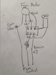
EKO 25. Blower not working. Replaced the blower and still nothing unless for some reason wired wrong. Blue wire to blue, brown to black and capacitor, and ground to screw underneath buss. Controller seems to be fine. Tested with 75 watt light bulb and it lit up when set to fire using brown wire from controller. What have I done wrong, what haven't I checked or what else could it be?
Thanks guys
 
My 40 010504_0914[00].jpg
 
Have you tried running the fun with a separate power supply to make sure it works? Have a voltmeter to check the leads to make sure you have the proper ones connected?


Green/ yellow is ground to the frame screw, both the wire from the control and motor combine onto the ground screw.m

Brown and blue are typical Euro colors, we use black and white normally for 120V.

Here is how my 6 year old EKO 40 is wired, should be the same for yours I think. Green/ yellow to ground screw

Brown #7 from control to black motor wire and capacitor
Blue #8 from control to blue to motor wire
Black from motor to capacitor
 

Attachments

  • Screen shot 2014-01-05 at 11.57.49 AM.png
    Screen shot 2014-01-05 at 11.57.49 AM.png
    33.2 KB · Views: 150
I placed a power cord in place of the brown wire from controller and screw under the orange buss on frame. Old blower had no response. Haven't tried new one yet. Did I test the old one correctly. There is a blue wire from controller that I have no idea what is. It connects through the orange connector to the blue wire of motor. Earlier when tested power from controller I used a 75 watt light bulb that lit up from brown wire from controller. Blue wire from controller gives 110 volt when connected to orange connector. Once unhooked it looses power except for a slight flutter on meter. Zenon says there is a diode in the controller that's why I used a light bulb to test for power. So controller seems to be giving power but neither old or new blower seem to work from controller. Still haven't manually powered new blower though.
Thanks for the picture mr.fixit
 
Just saw your post Bob. Your diagram looks just like what I have except for the yellow/green from the blower dose not connect to anything like represented in the picture above from mr.fixit. However the green/yellow from controller bolts to frame of blower inside plastic box.
Thank for the replies guys. Was feeling like I was lost in a forest. Still lost but at least have a life line.
 
Been a while but I still have a problem. What I know now is blower works fine when hard wired once I figured out that the blue wire is neutral. So my problem is the blue wire from controller. I get a slight voltage readout from the rk2001 controller on the neutral (blue) wire. The brown wire ( hot) does give variable voltage based on how fan is set. 50%=90v, 100%=118v exct. Does this mean I need a new controller or is there something to check.
 
I get a slight voltage readout from the rk2001 controller on the neutral (blue) wire. The brown wire ( hot) does give variable voltage based on how fan is set. 50%=90v, 100%=118v exct. Does this mean I need a new controller or is there something to check.
When your're measuring a voltage on the controller blue wire, and when you're measuring a voltage on the controller brown wire, what is it that the other lead of the voltmeter is connected to?

If you suspect the controller blue wire is not providing a neutral path, can you run an independent neutral wire in its place from elsewhere to see if the blue wire is the problem?
 
ewdudley When checking both wires I had the other wire on the frame of the boiler with fan attached and fan frame when detached from boiler. Are you saying I could run a neutral from something like the same circuit the controller is plugged into.

I believe there is a diode in the controller with these wires. Diode bad?
 
([Edit:] Backing up a bit, first of all when the controller is supposed to be running the fan you should of course see voltage across the neutral and hot wire going to the motor. If you're seeing voltage from the hot wire to the boiler chassis then you should see the same voltage going from the hot wire to the neutral wire. The discussion below assumes you do not see see a voltage going from the hot wire to the fan neutral wire.)

Are you saying I could run a neutral from something like the same circuit the controller is plugged into.
You could, but it shouldn't have to come to that. First I would pull the fuse, then remove input power/pump/fan power cover. Inspect to be sure the blue fan neutral wire is properly attached to the N fan terminal. If it is, with the fuse still removed, ohm out all the N terminals. They should all be electrically identical since all the N terminals are connected to the same trace on the rear vertical circuit board.

Be aware that the incoming L terminal will be hot the whole time with fuse in or out. You may prefer to kill the circuit to the controller and then verify there is no voltage across the incoming N and L terminals.

If there is not conductivity between the incoming N terminal and the fan terminal, then most likely the trace on the circuit board got smoked along the way. If you're confident you know why the trace got smoked the you can simply jumper from the incoming N terminal over to the fan N terminal (or simply move the fan blue wire over to the incoming N terminal) and go on about your business.

There are no diodes involved in the neutral wiring of the fan or pump circuits.
 
Last edited:
Thank you ewdudley. It appears like you just diagnosed my problem. I have no voltage between L and N and I get no continuity between fan N and any other N. Circuit board must have a burnt spot somewhere, odd I can't figure out how to open it up to check without destroying something. What caused it I have no idea. There were no special circumstances to cause it. Fired the boiler one day and worked fine but one day later did not.

The 1volt or so I was reading earlier from the N disconnected from blower and grounded to frame must have been power shorted on circuit board.

Thank you all. Sounds like i'll be calling Zenon about a new controller.
 
If all it is is a burned out trace on the circuit board you can just re-wire as described above.

DSCF7129.JPG DSCF7130.JPG DSCF7131.JPG

As you can see in the last photo there's just a trace from the incoming N terminal over to the two other N terminals. All you need to do is bypass the smoked trace by using a jumper from the incoming N terminal to the fan N terminal, or by simply wiring the fan neutral directly to the incoming N terminal.

(White wiring to the right of each N terminal is chassis ground, looks like they came up with something more substantial for that purpose.)

(RK 2001 controllers from P W Key don't need any "special circumstances" to provoke failure.)
 
Last edited:
If all it is is a burned out trace on the circuit board you can just re-wire as described above.

View attachment 123755 View attachment 123756 View attachment 123757

As you can see in the last photo there's just a trace from the incoming N terminal over to the two other N terminals. All you need to do is bypass the smoked trace by using a jumper from the incoming N terminal to the fan N terminal, or by simply wiring the fan neutral directly to the incoming N terminal.

(White wiring to the right of each N terminal is chassis ground, looks like they came up with something more substantial for that purpose.)

(RK 2001 controllers from P W Key don't need any " special circumstances" to provoke failure.)

Eliott are referring to the illuminated bus behind the hotwire? Thanx for the wiring lesson , as I own an EKO this could come in handy at some time in the future.

Huff
 
Eliott are referring to the illuminated bus behind the hotwire? Thanx for the wiring lesson , as I own an EKO this could come in handy at some time in the future.

Huff
Incoming hot 'L' terminal is on the left (looking from the inside) and trace goes over to fuse.

Incoming neutral terminal is next one to the right. The neutral trace goes up across the top and down to the pump N terminal and the fan N terminal.

Incoming chassis ground is the next one to the right of the neutral. There's a wire that goes to the pump ground terminal, and from there another piece of wire that goes over to the fan ground terminal.

RK2001PCB00.JPG

Same nine terminals from other side:

DSCF7133.JPG
 
Last edited:
Status
Not open for further replies.