
Help on Dual Boiler setup Coal-Propane
- Thread starter layoric
- Start date
-
Active since 1995, Hearth.com is THE place on the internet for free information and advice about wood stoves, pellet stoves and other energy saving equipment.
We strive to provide opinions, articles, discussions and history related to Hearth Products and in a more general sense, energy issues.
We promote the EFFICIENT, RESPONSIBLE, CLEAN and SAFE use of all fuels, whether renewable or fossil.
You are using an out of date browser. It may not display this or other websites correctly.
You should upgrade or use an alternative browser.
You should upgrade or use an alternative browser.
- Status
- Not open for further replies.

leon
Minister of Fire
Referencing the diagram, please note what needs to be done.
At the bottom of ther propain boiler and the K2 there are inlet/outlet pipe tappings that is where the temparature balancing pipe loop should be plumbed with a pump to feed the hot water from the K2 to the propain boiler.
Short of "creating a common return header to the propain boiler from the four zones" back to the propain boiler and installing the pump loop to balance the temperatures between the two boilers I dont see much of a solution as you have four separate thermostats.
Do this first(I would)
install black iron pipe with the second pump running continuously from the coal stoker to the propain unit. this gets you hot water all the time between the two boilers the year round.
Last edited:
ewdudley
Minister of Fire
Almost there. Since you are choosing to keep the LP boiler hot (which is a valid choice), the supply line from the coal boiler should be connected to the supply side of the LP boiler, and likewise the returns should be connected together. But the supply side connection would need to be somewhere on the inlet side of the the LP boiler pump, P2.How about this? I don't know if I need both check valves though.
The LP boiler is on and operates normally as if no changes were ever made to the system. It is P2 that feeds the loads, and the coal boiler is set up to flow in a reverse direction through the LP boiler, which keeps is hot enough that the LP boiler does not need to ignite.
The coal boiler call-for-heat would be activated by an aquastat on the return side of the LP boiler and also by a system call-for-heat.
So when there is a system call-for-heat both pumps activate. Some or all of the flow from the coal boiler pump, P1, feeds into P2 and goes out to the active zones and the excess flow (if any) goes back through the LP boiler, keeping it hot. If P2 flow exceeds P1 flow there will be some forward flow through the LP boiler and it will start to cool down. The LP boiler aquastat settings will need to be adjusted such that the coal boiler can catch up in time to keep the LP boiler from firing.
After the system call-for-heat is satisfied the coal boiler will continue to see a call-for-heat if the (newly added) aquastat on the return side of the LP boiler is not satisfied.
This is called a figure eight configuration that is commonly used to keep a standby boiler hot, but ready to fire if the primary boiler goes offline.
Last edited:
maple1
Minister of Fire
I was laying in bed this morning figuring this all out, then I come on here & see you guys are ahead of me.
")
I have a question though to add to the dialogue - what exactly do you have for circ pumps now at each location?
I am guessing the propane circ is a constant speed pump that is flowing too much flow for when just one or two zones are open. You would see much better zone (and maybe also system) performance if that pump (P2) was a Grundfoss Alpha or the such - and I would hazard a guess that your water hammer issue would disappear. You could possibly reduce control issues using an Alpha there also - just plug it into power, it will sense zones opening & closing on its own and maintain proper flow, once you get the baseline flow (delta P) tuned in.
Referring to ewdudley's help above, you could use a Johnson A419 controller to control the call for P1 to start & stop, and surface mount the sensor for it on the LP return pipe, as far in towards the boiler as you could get it. Or onto the surface of the water jacket itself, at the return tapping - depending on access to the jacket. Then if you wanted to eliminate the chance of that stuff circulating cold water from the coal unit if it ran out of coal or something like that, you could also use one of your 4006 stats (whichever one makes on rise) sensing at your coal boiler, that would interrupt the electricity between the Johnson & P1 if the coal boiler went cold.
Also don't know exactly what kind of setup that is for DHW off the coal unit? And it still looks like your expansion is on the wrong side of the circs - that said without knowing distances between everything though. How far apart are the boilers? Thinking you likely would only need one expansion tank setup for the system.
ewdudley
Minister of Fire
The aquastat relay would be wired to the coal boiler T-T terminals in addition to all the system call-for-heat contacts, all 'wired-OR' together.Then if you wanted to eliminate the chance of that stuff circulating cold water from the coal unit if it ran out of coal or something like that, you could also use one of your 4006 stats (whichever one makes on rise) sensing at your coal boiler, that would interrupt the electricity between the Johnson & P1 if the coal boiler went cold.
The Keystoker has a conventional L8124A 'triple aquastat' that would turn off P1 on low-limit. Also I think would need a check valve to keep P2 from back-feeding coal boiler when P1 not pumping.
maple1
Minister of Fire
Ah, OK on the 8124. I've got one of those in my system. It kicks out my main circ when storage is cold, just before it kicks on the electric boiler which has it's own circ.
I have no experience with either a gas boiler, or a coal boiler - so buyer beware on anything I say here.
Likely yes on the check - unless P1 has one built-in? Which could be the case, depending on what it is & if the installer removed it on installation.
I have no experience with either a gas boiler, or a coal boiler - so buyer beware on anything I say here.
Likely yes on the check - unless P1 has one built-in? Which could be the case, depending on what it is & if the installer removed it on installation.
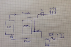
OK, new diagrams, original setup shows some return lines from the rooms - they are of course shortened down. I also have two proposed changes. What I believe are a series setup, and parallel. It seems that the installer set it up as a parallel system - almost, although I believe that wasn't what he told me he was going to do...
This is the setup as it is NOW.

This I believe changes it to run in SERIES.

This should be the setup in PARALLEL.

OK, could someone tell me what I would be missing to install where in the series and parallel examples above? The original installer is supposed to come over tomorrow at noon to fix this debacle.
This is the setup as it is NOW.
This I believe changes it to run in SERIES.
This should be the setup in PARALLEL.
OK, could someone tell me what I would be missing to install where in the series and parallel examples above? The original installer is supposed to come over tomorrow at noon to fix this debacle.
ewdudley
Minister of Fire
Using the third drawing, just move the LP boiler pump up above the tee that feeds over to the return side of the coal boiler and your're good to go.
Bob Rohr
Minister of Fire
OK, new diagrams, original setup shows some return lines from the rooms - they are of course shortened down. I also have two proposed changes. What I believe are a series setup, and parallel. It seems that the installer set it up as a parallel system - almost, although I believe that wasn't what he told me he was going to do...
This is the setup as it is NOW.
View attachment 142325
This I believe changes it to run in SERIES.
View attachment 142326
This should be the setup in PARALLEL.
View attachment 142327
OK, could someone tell me what I would be missing to install where in the series and parallel examples above? The original installer is supposed to come over tomorrow at noon to fix this debacle.
Does the coal fired boiler provide the DHW with a tankless coil somehow?
Not sure why series piping is required if DHW is not provided by a "hot" boiler?
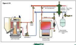
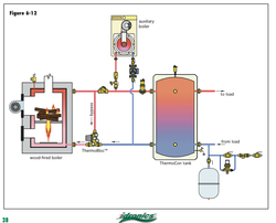
Super simple ways to parallel boilers without pumping and flow conflicts.
Here are some piping examples. The tank or separator, in the drawings may not be needed or wanted, just install the ZVs there, like the hand drawn example.
I would protect the coal boiler with a mix valve.
A link to a journal that may help the installer with the concepts.
http://www.caleffi.com/sites/default/files/coll_attach_file/idronics_10.pdf
Ignore all this if for some reasons the boilers MUST be series piped.
Attachments
First, thank you!Does the coal fired boiler provide the DHW with a tankless coil somehow?
Not sure why series piping is required if DHW is not provided by a "hot" boiler?
Super simple ways to parallel boilers without pumping and flow conflicts.
Here are some piping examples. The tank or separator, in the drawings may not be needed or wanted, just install the ZVs there, like the hand drawn example.
I would protect the coal boiler with a mix valve.
A link to a journal that may help the installer with the concepts.
http://www.caleffi.com/sites/default/files/coll_attach_file/idronics_10.pdf
Ignore all this if for some reasons the boilers MUST be series piped.
Yes, coal boiler has DHW setup.
What wiring must be changed to finish as parallel, and what is the concept of a parallel setup? I read some other posts about parallel setup, but didn't understand it entirely. From what I figure, the parallel setup will allow both boilers to function independently, but how is that to happen with the zone valves powered by the propane boiler? The same would be true if the ZV's were moved to the coal boiler... Is it possible to wire them to both at the same time, but just power up only one or the other?
Thank you!Using the third drawing, just move the LP boiler pump up above the tee that feeds over to the return side of the coal boiler and your're good to go.
What wiring will have to occur as well? What actually happens with a parallel system?
maple1
Minister of Fire
The zone valves shouldn't be powered by a boiler - they should be powered by the thermostats.
Edit: aren't those red arrows in your zone flows pointing in the wrong direction? And if you just discovered that pump was pumping the other way, does that mean the valves are installed backwards? Would still like to know what you have for a circ there.
Edit: aren't those red arrows in your zone flows pointing in the wrong direction? And if you just discovered that pump was pumping the other way, does that mean the valves are installed backwards? Would still like to know what you have for a circ there.
leon
Minister of Fire
=======I was laying in bed this morning figuring this all out, then I come on here & see you guys are ahead of me.
I have a question though to add to the dialogue - what exactly do you have for circ pumps now at each location?
I am guessing the propane circ is a constant speed pump that is flowing too much flow for when just one or two zones are open. You would see much better zone (and maybe also system) performance if that pump (P2) was a Grundfoss Alpha or the such - and I would hazard a guess that your water hammer issue would disappear. You could possibly reduce control issues using an Alpha there also - just plug it into power, it will sense zones opening & closing on its own and maintain proper flow, once you get the baseline flow (delta P) tuned in.
Referring to ewdudley's help above, you could use a Johnson A419 controller to control the call for P1 to start & stop, and surface mount the sensor for it on the LP return pipe, as far in towards the boiler as you could get it. Or onto the surface of the water jacket itself, at the return tapping - depending on access to the jacket. Then if you wanted to eliminate the chance of that stuff circulating cold water from the coal unit if it ran out of coal or something like that, you could also use one of your 4006 stats (whichever one makes on rise) sensing at your coal boiler, that would interrupt the electricity between the Johnson & P1 if the coal boiler went cold.
Also don't know exactly what kind of setup that is for DHW off the coal unit? And it still looks like your expansion is on the wrong side of the circs - that said without knowing distances between everything though. How far apart are the boilers? Thinking you likely would only need one expansion tank setup for the system.
OK, new diagrams, original setup shows some return lines from the rooms - they are of course shortened down. I also have two proposed changes. What I believe are a series setup, and parallel. It seems that the installer set it up as a parallel system - almost, although I believe that wasn't what he told me he was going to do...
This is the setup as it is NOW.
View attachment 142325
This I believe changes it to run in SERIES.
View attachment 142326
This should be the setup in PARALLEL.
View attachment 142327
OK, could someone tell me what I would be missing to install where in the series and parallel examples above? The original installer is supposed to come over tomorrow at noon to fix this debacle.
================================================================================================================================================
As my British friends would say "thats a real "cock up"
I hope the installer knows how to separate and segregate everything the way he was supposed to with a common return header for ALL the return lines to go back to one boiler.
Part of the problem lies with the fact that the boilers are not next to each other to allow for the single pipe loop connection to balance the temperatures between the two boilers and installing a ball valve to separate the two boilers if needed as mine is.
The fossil fuel boiler in my case has two pumps on the suction side (bottom outlet) one to pump water between the two boilers to balance the temperature AKA temperature balancing loop when I am burning wood and coal along with oil and the second pump to pipe the hot water to the single loop that heats the house with the return water coming to the oil boiler.
I have a single common air scoop with a bladder tank and B+G air vent for both boilers two B+G right angle check valves and a second air vent to prevent ther highest elbow from becoming air locked and having the coal and wood boiler go to steam.
Single pipe low pressure steam (<15PSI) is so much simpler in my opinion.
I hope he straightens it out for you with little if any cost to you.
Last edited:
ewdudley
Minister of Fire
Don't do a series configuration.
If you want a parallel setup as Rohr is suggesting, where each boiler is independent and each boiler stays cool until it is activated, then use your third diagram, but add a check valve or pump internal flow-check for each boiler to prevent either boiler from pumping back through the other. This doesn't really address your water-hammer, overheat, or DHW recovery problems directly. The overheat and DHW recovery problems can probably be helped by tuning the KAA-2 better (google for KAA-2 tuning and follow the nepacrossroads.com links). The water-hammer problem might be helped by using a smaller pump or maybe a deltaP pump as suggested, but it may require water hammer arresters or a different type of zone valve to solve that problem.
If you want a figure-eight setup where the coal boiler is the primary boiler and the LP boiler is the standby boiler that is kept hot all the time, then use your third diagram, but move the LP boiler up above the tee that is currently just above that pump in the third diagram. In this setup the LP boiler pump feeds the loads and the coal boiler pump keeps the LP boiler hot. This would be the best configuration for helping to solve the overheating and DHW recovery problems because the LP boiler would add some amount of buffering, and it would probably help a lot in mitigating the water-hammer problem because not all the pump flow is being forced through the load circuits.
Be aware that if you go with the figure-eight configuration then the LP boiler will stay hot all the time and may lose a fair amount of heat up the flue. Also, although with the figure-eight configuration the LP boiler will take over automatically if the coal boiler goes offline, when it does you there will be parallel flow through the coal boiler until the coal boiler is manually isolated (or automatically isolated with a powered valve).
Ideally you would want a small (e.g., 30-50 gallon) buffer tank set up as a hydraulic separator that would be fed by either the coal boiler or the LP boiler independently.
Last edited:
The transformer is on the lp side, so the zone valves are powered by that, and t-stats. No, I believe the arrows are correct, since I open the zv manually then it gets hot immediately above it.The zone valves shouldn't be powered by a boiler - they should be powered by the thermostats.
Edit: aren't those red arrows in your zone flows pointing in the wrong direction? And if you just discovered that pump was pumping the other way, does that mean the valves are installed backwards? Would still like to know what you have for a circ there.
maple1
Minister of Fire
Also, although with the figure-eight configuration the LP boiler will take over automatically if the coal boiler goes offline, when it does you there will be parallel flow through the coal boiler until the coal boiler is manually isolated (or automatically isolated with a powered valve).
What if, along with moving the LP circ as you suggested, he also turned it around so it was pumping up rather than down? (The way he thought it was pumping first). And either used a checked circ on the coal loop or put in a check valve there? Although the hot coal water would then need to go through the LP boiler before it got to the zones. Also sounds like there is still a question on whether the zone valves are pointing the right way, since there was confusion about which way the water was going.
On the DHW thing - I assume that setup is a tankless coil in the coal boiler, in series with an electric hot water heater? Don't think that has been clarified for sure. If so, I think there are a couple of ways to improve that situation. First, don't mix down between the coil & electric heater as shown. Rather, put a mixer on the DHW-out of the electric water heater, between it and the taps. If that was still not satisfactory, you would for certain have all the hot water you would need if you added a small recirc pump (I have a B&G Ecorcirc E^3) that would circulate the water between coil & heater when there was no hot water being used. I control mine with a Johnson A419 in a FPHX setup. Also don't know how big the electric heater is either - but the bigger the better for that, if a lot of hot water is being used.
maple1
Minister of Fire
No, I believe the arrows are correct, since I open the zv manually then it gets hot immediately above it.
How can that be, if the pump is pumping down?
How can that be, if the pump is pumping down?
maple1
Minister of Fire
The transformer is on the lp side, so the zone valves are powered by that, and t-stats.
OK, I guess maybe I could clarify a little. They may be powered by a transformer on the LP side, but they are activated and controlled by the stats. The stats activate a ZV on call for heat, the ZV opening then starts the circ pumping usually by an enclosed end switch in the ZV. The tranformer power supply is a constant and doesn't really matter where it comes from - it gets switched by the stats. So really neither boiler controls the zone valves.
I think.
ewdudley
Minister of Fire
That would take care of the DHW reserve problem nicely, which removes the main advantage of going with the figure-eight.On the DHW thing - I assume that setup is a tankless coil in the coal boiler, in series with an electric hot water heater? Don't think that has been clarified for sure. If so, I think there are a couple of ways to improve that situation. First, don't mix down between the coil & electric heater as shown. Rather, put a mixer on the DHW-out of the electric water heater, between it and the taps. If that was still not satisfactory, you would for certain have all the hot water you would need if you added a small recirc pump (I have a B&G Ecorcirc E^3) that would circulate the water between coil & heater when there was no hot water being used. I control mine with a Johnson A419 in a FPHX setup. Also don't know how big the electric heater is either - but the bigger the better for that, if a lot of hot water is being used.
So now I would say don't do a series, don't do a figure-eight, and go ahead with figure 3 above with the addition of appropriate check valves or integrated flow-checks. The water-hammer and overheating problems can be dealt with separately.
ewdudley
Minister of Fire
@layoric: How about a close up well lit picture of the LP boiler pump so we can see for ourselves what direction it is pumping.No, I believe the arrows are correct, since I open the zv manually then it gets hot immediately above it.
How can that be, if the pump is pumping down?
ewdudley
Minister of Fire
Ahh, but the coal boiler pump P1 is pumping up in the as-currently-plumbed diagram!No, I believe the arrows are correct, since I open the zv manually then it gets hot immediately above it.
How can that be, if the pump is pumping down?
maple1
Minister of Fire
My mind is getting muddied between the now & then - think it's time for me to go pile wood for a few hours...
Bob Rohr
Minister of Fire
Would you consider another option for DHW? It seems the only reason series piping is being considered to to always keep the coal fired boiler hot for DHW?
Series piping is never a good option for multiple boilers. You are always flowing thru and un-fired boiler. So a portion, possibly a large portion of the energy is going up the flue pipe and through jacket loss of dual boilers.
Maybe consider a basic LP fired WH, electric, or a tankless inline with the DHW coil. Off season (non heating season) Dhw is generated without firing all that cast iron, fluid volume and flue piping loss.
With series your dhw costs could offset what you are trying to save with coal as a source?
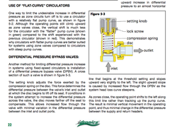
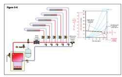
Water hammer is generally caused by zone valves closing off, or trying to, against high velocity flow. A PAB pressure activated bypass is a simple way to eliminated that IF the single speed circ is sized properly to begin with. The PAB basically attempts to flatten the pump curve, it should be considered anytime more than 4 zone valves are on a fixed speed circ.
Or a variable speed delta P circ Grundfos Alpha, Wilo ECO,,Armstrong Compass, B&G Vario Eco are all excellent circs for zone valved jobs.
Series piping is never a good option for multiple boilers. You are always flowing thru and un-fired boiler. So a portion, possibly a large portion of the energy is going up the flue pipe and through jacket loss of dual boilers.
Maybe consider a basic LP fired WH, electric, or a tankless inline with the DHW coil. Off season (non heating season) Dhw is generated without firing all that cast iron, fluid volume and flue piping loss.
With series your dhw costs could offset what you are trying to save with coal as a source?
Water hammer is generally caused by zone valves closing off, or trying to, against high velocity flow. A PAB pressure activated bypass is a simple way to eliminated that IF the single speed circ is sized properly to begin with. The PAB basically attempts to flatten the pump curve, it should be considered anytime more than 4 zone valves are on a fixed speed circ.
Or a variable speed delta P circ Grundfos Alpha, Wilo ECO,,Armstrong Compass, B&G Vario Eco are all excellent circs for zone valved jobs.
Attachments
What I meant was the zone valves transformer is powered on the circuit on the boiler.The transformer is on the lp side, so the zone valves are powered by that, and t-stats.
OK, I guess maybe I could clarify a little. They may be powered by a transformer on the LP side, but they are activated and controlled by the stats. The stats activate a ZV on call for heat, the ZV opening then starts the circ pumping usually by an enclosed end switch in the ZV. The tranformer power supply is a constant and doesn't really matter where it comes from - it gets switched by the stats. So really neither boiler controls the zone valves.
I think.
- Status
- Not open for further replies.
Similar threads
- Replies
- 9
- Views
- 2K
- Replies
- 5
- Views
- 420
- Replies
- 4
- Views
- 1K
- Replies
- 0
- Views
- 945