1988 Breckwell P24 Freestanding Stove Wiring issues

  • Active since 1995, Hearth.com is THE place on the internet for free information and advice about wood stoves, pellet stoves and other energy saving equipment.

    We strive to provide opinions, articles, discussions and history related to Hearth Products and in a more general sense, energy issues.

    We promote the EFFICIENT, RESPONSIBLE, CLEAN and SAFE use of all fuels, whether renewable or fossil.
Status
Not open for further replies.

SFSurfdude

New Member
Oct 23, 2014
23
Stockton, Ca
I have spent the last three months trying to sort this out, I have the above listed stove. Last season it worked like a champ. Well, at the end of the season it failed to start up, so I sent the PC Board off to be checked and it is OK. When I disconnected the PC Board I removed five wires from four positions on the PC board as well as the Molex connector. The diagram I made has come up missing for the wiring, Ive spent alot of time trying to figure it out but Im not willing to take the chance of making a bad connection and ruining my stove. It is my only heat source and the nights are getting very cold.
The wires I removed from the PC Board are the following colors: Yellow, Black, Grey, Blue and Pink
The PC Board is labeled as follows: Yellow, White, Black and Red
The 8 pin Molex connector seems to be able to be connected in either direction, no snap to indicated which way it should be connected.
The pink wire goes to the terminal strip
Blue goes to the high temp thermodisc
grey goes to normal/high fan
Black and yellow are obvious.
Any help is appreciated, this is a good unit and would like to keep using it. The molex connector Im not sure how to resolve. Thank you in advance...
Here are the pics of the wires and pc board connections: Stove wires.jpg DSCN1183.JPG
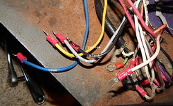
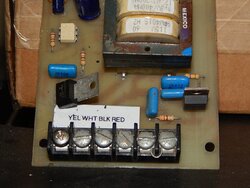
 
I can email you an OM for a P24 the oldest I have is the 1989 version. It does have a wiring diagram that may be helpful
 
Thanks for the wiring diagrams, unfortunately I cant make heads or tails out of this. With a lack of repair people etc etc. My best guess is I will need to buy a 50000 BTU
Gas Floor heater for my house. It appears Ive shot myself in the foot on this one loosing that 3X5 card with the notations of where those wires go on that PC Board.
I dont have the where with all to sabotage this stove trying either and ruining components... Worst case senerio I can part it out in order to recoup some of the monies Im loosing.
 
Unfortunately I dont, but Im not the type to be a quitter. So Im looking on youtube trying to learn how to read wiring diagrams. I love this stove and it worked perfectly, its going to cost around 500. to make the switch to gas so my motivation is to get this resolved.
 
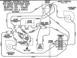
This diagram is the oldest I could find. It goes back to '92. Hope it may help you.

92breckwell.jpg
 
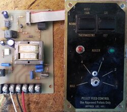
Here's a picture of the control board with the molex multiconnector in place:
old%20Breckwell3.jpg
 
  • Like
Reactions: Lake Girl
The wire you have marked as light grey - is it actually pink?
You are absolutely correct, the wire marked light grey is actually a pink wire as you suggested. When I initially signed up as a youth in the Army, I thought I wanted to be a wireman in the Signal Corps. After testing, they informed me that I had a very minor colorblindness problem which disqualified me from that position. Now couple with Macular degeneration going on theres a real need for me to avoid said wiring work period... My issue is going to resolved in a couple of days.
 
Here's a picture of the control board with the molex multiconnector in place:
View attachment 142389

The picture is my exact analog set up my p24 has. The minor difference are the wires I see on the four hookup positions. I am learning that the wire colors may differ from the wire colors as indicated on the wiring diagram. In any event, within a couple days my Breckwell issue I brought upon myself is going to be resolved. I was a complete retard looking at any wiring diagram a few days ago, but refusing to allow a good stove to go to waste I began the learning process of HOW TO...
As my luck and pleading for help would have it, I found a local technician to resolve this for me. Learning is always great, but my wood flooring project needs my attention, I cant put the feeling behind me that somehow Im playing "Wire Roulette" when I look at this wire mess...
Thanks to all who took the time to assist me with this issue, I deeply appreciate your effort...
Regards
SFSurfdude
Stockton, Ca (When traveling past Stockton, keep going. Do not even stop in this town for fuel, food or anything...)
This is where I came up with the term "Criminally Ignorant" This is where Gangs are #1 and the residents here rationalize behaviors that are insane, dial back 4 or so generations of the same and you have a real mess of people without hope for anything as we know it.
 
This is where I came up with the term "Criminally Ignorant" This is where Gangs are #1 and the residents here rationalize behaviors that are insane, dial back 4 or so generations of the same and you have a real mess of people without hope for anything as we know it.
That's just sad and without intervention, the younger ones don't have role models for a decent life...
 
Apparently Stockton is bankrupt so the police force will likely disappear too... Crime stats are nasty. How did you end up in Stockton and how long have you been there? Forum is here for when you want to talk pellets; Inglenook for when not pellet related - leave politics out of both though...
 
Pd cash 50K for home 1 yr ago, mother was aging then died two months later.
Still waiting on my tech, He is going to review an old job He did in Sacramento with the same stove. Ive done all the maintenance on the stove including sanding all carbon off fan blades, replacing gaskets, sanding off light rust and blowing out the motors with my compressor. I saw that people mention oiling the motors but I failed to see any specific oiling point but will research further.The one thing I have yet to do is find the appropriate insulating material for the back wall to protect the motors I assume from the heat of the firebox.
 
It looks like what I may need the answer to is as in the above example posted by Stevenson on Oct 26th 2014 would be where the particular colored wires are going to or their destination so that I can connect my wires which are a different colors. My tech is having equally a difficult time sorting this out as well
 
Is there any chance that you might be able to tell me the locations or components the yellow red black and white wires are going to?

My personal/practical experience with pellet stoves is entirely based on servicing my Quest Plus. On a Breckwell I have no hands on experience, but wait a sec... the website where I found the pic of the P24 control actually has some info on the wiring that could help you a long way. Have a look at this:

http://www.hearthtools.com/parts/Breckwell_help.htm

Eventually we may have to do some reverse engineering, you know, step by step analyze each individual component, and how the overall functionality is. Especially the safeties are important to have wired in the right order. A Breckwell stove seems to be a bit different from a Whitfield.
We could really do with a proper wiring diagram of a 1988 P24. Maybe a fellow P24 owner will chime in to help, when they see this.

Reverse engineering could be as simple as this to start with: On a blank piece of paper you draw each component in the stove: Blowermotors ( and their wirecolors ), safety switches ( and their wirecolors ), ignitor ( and its wirecolors ), auger motor ( and its wirecolors ), control board and terminal strip. Then you take a nice sharp photo of this drawing and post it in here. Together I'm sure we will be able to solve the puzzle;)
Note: If you decide to make a drawing for reverse engineering, then I strongly suggest you to make it in the Breckwell style like the one I posted earlier in the thread of a P24 from1992.
 
Last edited:
Well as it stands now Ive wired up the control board incorrectly which i the leat of the problem. I broke of a resistor (3 prong) from fooling with the wiring, actually knocked it off. So I give up...
Im going to not give up so easy, Im going to go with the wiring for old pellet stoves as posted on this site as a last chance for my stove. Ive been running it by manualy placing pellets in the burn pot which results in a flash explosion if you arent careful. Enough said. I found a recycle timer on Ebay the title is: ABB SACC Solid State Econo timer relay recycle New in Box. Can this work for a pellet stove? to regulate the hopper feed rate? Its getting mighty cold, my chihuahua and I are fairly miserable and I would love to put this entire issue in my "resolved" filing box.
One other timer which I prefer as the delays are appropriate is a: Crouzet Syrelec ODRU220A Interval Timer Repeat cycle relay but it is 24Vac so Im assuming it could be used to activate a 120v auger somehow with the addition of another type of mechanism to which I dont know what to call it.
My electronics and electricity knowlege is limited but with how chilly its getting I need to do something (barring burning down my house)


$_57.JPG
ABB SSAC Solid State Econo Timer Relay Recycle NEW IN BOX

Mouse over image to zoom
  • $_14.JPG
  • $_14.JPG
  • $_14.JPG
  • $_14.JPG
ABB
 
Can the resistor be repaired? Much safer to use the component designed to operate the stove...

I would start drawing (or at least listing) the diagram that Stovensen suggested - Component and what coloured wires are attached to it i.e. room convection blower pink & white wires, exhaust combustion blower black & white, auger orange and grey....
 
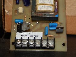
breckwell pc.jpg I would imagine the component can be replaced by removing the old remaining prongs and re soldering another one in its place, if Im not mistaken its a limiting resistor? But Ive seen them at radio shack for 2.00.
Ive been hesitant to draw this as instructed as Im not good at doing that but I will do it at the best of my ability I suppose.View attachment 147167
 
Attachment didn't show up ... Not worried about your artistic ability, just want to help with getting some heat!
 
Thank you, I will draw it out today after I get done with my errands. If you look at the control board photo in this post I previously placed the limiting resistor is immediately above the "Yellow" wire screw. It is three pronged and has metal sticking out the top of it.
 
Status
Not open for further replies.