looking for advice on my storage tank build

  • Active since 1995, Hearth.com is THE place on the internet for free information and advice about wood stoves, pellet stoves and other energy saving equipment.

    We strive to provide opinions, articles, discussions and history related to Hearth Products and in a more general sense, energy issues.

    We promote the EFFICIENT, RESPONSIBLE, CLEAN and SAFE use of all fuels, whether renewable or fossil.
Status
Not open for further replies.

kjahnz

Burning Hunk
Oct 14, 2012
139
Minnesota
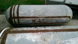
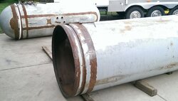
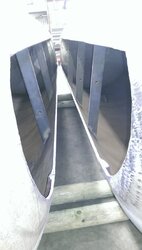
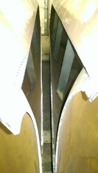
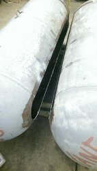
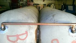
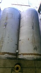
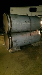
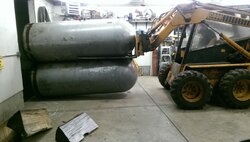
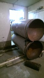
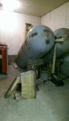
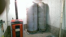
I've been putting it off long enough, and started my storage tank build. In general, I'm putting two 500 gal. Propane tanks vertically. That part is coming along nicely.
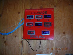
The advice I'm looking for is a simple temp measuring and digital display idea. I think four locations from top to bottom would be nice. I'm thinking the thread talking about WiFi capability is to high tech, nice features, but not necessary for me. Any suggestions?


Maybe I should bring this question to that other thread?
 
Last edited:
I used four of these on my setup.

https://www.grainger.com/product/TA...m/rp/s/is/image/Grainger/5XL18_AS01?$smthumb$

One for the top of each tank and one at roughly 20% up from the bottom of each tank. More measurements would be "neat" but in terms of adjusting how you're running your system all you really need to know is supply (top) and return (bottom) temps. I guess knowing what's going on in the middle will help you figure out how much more heat you have in there but after a few weeks of running you're going to have that figured out without the gauges...
 
  • Like
Reactions: flyingcow
Hey KJ,

Depending on each person's goal there could be many ways to go. My goal is to monitor tank temperature status (for peace of mind) and as input for calculating pounds of wood required. Originally I used two of the Azel DS-60P units. They are powered by battery (CR2032-3 volt) or 24vac, and they have 2 sensors with 2 readouts. The wires can be extended to longer lengths. These worked pretty good using 4 sensors and 4 readouts. They are NOT illuminated but do have a maximum and minimum logging option for both sensors.

Over this summer, I put together a different setup using the Sure Electronics as easternbob linked to. For this I used 5 sensors and 5 readouts (illuminated). These are located at the bottom, 25%, 50%, 75% and the top. This is a bit more accurate due to the one additional sensor location, and the readouts are much more visible. From across the room where the laptop sits, the readouts are easily viewed and keyed into the formula for determining how many pounds to burn. The unit I went with comes with 2 sensors and is powered by a common wall wart, maybe 8vdc minimum. The wires can be extended just as the Azel. Went with the 2 sensor unit from parts-express.com, just to have spare sensors. Models ME-TM42123 (blue) and ME-TM41123 (red).

Azel.jpg SureBack.jpg SureFront.JPG TankTemps.JPG WallWort.jpg
 
i have one sensor towards the bottom of one of my 500 gallon tanks. I had one on each tank at first to make sure they charge and discharge evenly. I have no problem running it off one sensor like that. I know how much energy is in the tanks over all by the psi. When that one sensor reads 120 - 130 F I know to fire the boiler or I may only have a warm shower in the near future. I don't even have a thermowell, I just taped a sensor to the tank and covered with insulation. I can look at the temp on the boiler and know how hot the water going into the tanks are. that is the temp at the top of your tank. Sure more gauges look nice, but it's really not a must. If I had the time, money and desire, I probably would have done top middle and bottom one one tank and top and bottom on the other.
 
What exactly is that you have your Sures mounted in?

This is a simple wood frame using 1/2" x 3" poplar, glued and screwed. Faceplate is from 1/16" sheet metal, cut to fit, add holes and paint.


Box.JPG
 
I have a couple pics of my storage project, now I am getting closer to having to make some hard decisions.
 

Attachments

  • IMAG0135.jpg
    IMAG0135.jpg
    182.1 KB · Views: 258
  • IMAG0139.jpg
    IMAG0139.jpg
    139.9 KB · Views: 226
I am at a stage where I need to cut holes for water in and water out, temp sensors and anything else that might be needed. 4 3/8 ports for temp wells, cold water out and hot water in and out.
 

Attachments

  • IMAG0164.jpg
    IMAG0164.jpg
    115.1 KB · Views: 264
  • IMAG0165.jpg
    IMAG0165.jpg
    113.7 KB · Views: 251
  • IMAG0167.jpg
    IMAG0167.jpg
    135.5 KB · Views: 233
I want to run this by some of you with storage as part of your heating system. In the pic I am showing one cold water port and two hot water ports connected with an elbow and a "T" that will continue to my boiler and a weighted check valve to my emitters. My question is will I draw off the top of both tanks or Will I only draw off the nearest tank? My goal is to draw heat off of both evenly. Thanks.
 

Attachments

  • IMAG0176.jpg
    IMAG0176.jpg
    160.4 KB · Views: 248
  • IMAG0177.jpg
    IMAG0177.jpg
    136.4 KB · Views: 238
  • Like
Reactions: ewdudley
I want to run this by some of you with storage as part of your heating system. In the pic I am showing one cold water port and two hot water ports connected with an elbow and a "T" that will continue to my boiler and a weighted check valve to my emitters. My question is will I draw off the top of both tanks or Will I only draw off the nearest tank? My goal is to draw heat off of both evenly. Thanks.
It's all one tank until you get almost to the top, so nothing to worry about. Even if it was two separate tanks the buoyancy of the water in the far tank would even things out pretty well.
 
Two panels I put together using panel meters similar to those shown above which use DS18B20 sensors.DSCN1887.JPG
 

Attachments

  • DSCN2096.JPG
    DSCN2096.JPG
    112.1 KB · Views: 242
Lots of pics, some heavy lifting. Plumbing is next.
 

Attachments

  • IMAG0195.jpg
    IMAG0195.jpg
    133 KB · Views: 171
  • IMAG0199.jpg
    IMAG0199.jpg
    119.1 KB · Views: 259
  • IMAG0202.jpg
    IMAG0202.jpg
    158.5 KB · Views: 238
  • IMAG0203.jpg
    IMAG0203.jpg
    102.2 KB · Views: 230
  • IMAG0206.jpg
    IMAG0206.jpg
    136.8 KB · Views: 231
  • IMAG0208.jpg
    IMAG0208.jpg
    135.8 KB · Views: 207
  • IMAG0212.jpg
    IMAG0212.jpg
    136.9 KB · Views: 200
My main question is if I can load storage and supply heat to the emitters at the same time?
Then once the wood boiler shuts down, my primary loop pump(I did not label..oops) will circulate thermo storage through the primary loop supplying heat to my mixing valve and emitter pump?
I am hoping that placing the spring che k valve up stream of my propane boiler supply(load) isolates it from storage.
The weighted check valve between the wood boiler and storage, isolates the wood boiler while the primary loop pump allows storage to supply the load to the emitters?
Almost all of the plumbing schematics in the caleffi idronics show thermo storage charged through dedicated supply and demand ports, and the primary loop has it's own dedicated thermo storage ports.
Any feedback is appreciated, thanks.
I quess, I am hoping my boiler protection (mixing valve) prevents flow through it when the wood boiler is shut down....
 

Attachments

  • Plumbing Sketch 2.jpg
    Plumbing Sketch 2.jpg
    79 KB · Views: 226
Last edited:
Status
Not open for further replies.