1988 Breckwell P24 Freestanding Stove Wiring issues

  • Active since 1995, Hearth.com is THE place on the internet for free information and advice about wood stoves, pellet stoves and other energy saving equipment.

    We strive to provide opinions, articles, discussions and history related to Hearth Products and in a more general sense, energy issues.

    We promote the EFFICIENT, RESPONSIBLE, CLEAN and SAFE use of all fuels, whether renewable or fossil.
Status
Not open for further replies.
Hi Surfdude, the component next to "yellow" wire screw has Q2004F 31 written on it. That is a Triac in a TO-202 housing. The digit '4' indicates that it is a 4 amp version. Radio Shack has a replacement for about $ 2 that most likely will work, provided that it is pin to pin compatible. They should know at Radio Shack.
I have attached the datasheet for the Q2004F 31 Triac below this text.
Looking forward to study your drawing of the wiring with cable colors etc. We are ready here to help you the best we can.

Keep us posted
Bo
 

Attachments

  • Triac Q2004F datasheet.pdf
    225.4 KB · Views: 256
Ive completed my version of an electrical wiring diagram for my P24 Pellet Stove. As reluctant as I was to do this as an option simply wasted valuable time. Im smiling thinking the real motivator was the awful cold, now the impending storm on its way... So please forgive my "version" it may not be according to known standards but maybe that is why I was a Painting Contractor and not an electrician. Frankly I feel good about getting this done. If (Im sure) you may have any questions pls. of course ask me I will get an answer back quickly, most of all many thanks for your time helping me getting this done. I will resolve the 4 amp Triac repair/soldering I need to do.
 

Attachments

  • 1988 breck.pdf
    1.3 MB · Views: 435
  • 1988 breck1.pdf
    731.2 KB · Views: 403
Also I forgot to label the wires on the power supply going to the terminal strip. One which is screwed independently away fm the term strip is the ground. The one next to it is white the top one is black.
 
Stovensen is going to be able to give you the key on this by telling you where the yellow, white, black and red wires run to off his board. All the wiring diagrams that I have looked at have 6 wires going to the board not 4 (or 5 in your case). Can see why this has been driving you nuts...
 
This is good news to me and my little dog Yohdah... When I go out to go food shopping today I am going to splurge and buy some bags of pellets in advance of this potential success...
 
Thanks for the drawing, Surfdude. Just got back home a little while ago after driving through some heavy snowfall, which later turned into heavy rain.
Now this is something of a puzzle for sure, but I've heard that a little exercise for the neurons should be good for elderly people like me ( I'm 59 ).

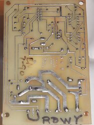
I have added to the drawing, what we know so far. Also, I have added some text on your picture of the pcb in order to determine exactly what is connect to the terminals on the pcb. Very important. We can see that the two input terminals of the primary side of the transformer need to be energized all the time by the phase (L) and the neutral (N), 120 Volt/60 Hertz, otherwise the electronics won't work at start up.
Surfdude, please study my findings so far, and do correct it, if anything appears uncorrect.

A Breckwell P24 from 1988 differs from my Whitfield Quest Plus on several points... in particular the fact that it doesn't have an air flow switch:rolleyes:
A P24 also has an extra snap switch of the N.O. type ( Normally Open ). I have found a very useful and detailed description of the overall functionality of the safety switches on a P24 on the Hearthtools website. This information really opened my eyes on how these important safety switches operate:

Limit switches:
Most Breckwell's have 3 switches: a. One 60T21 high Limit (over heat) thermo Switch. Normally Closed (N.C.).Click here for Test
If the stove gets over 300 Deg this switch will stop the supply of pellets even if the manual button is pressed. The combustion blower and convection blower will stay running to burn up the rest of the pellets and to cool the stove down .
b. Auger thermodisk 60t22 switch. Normally Open (N.O.) Click here for Test
This switch will close at 110 deg. allowing power to come from the control boards yellow wire after the 15 minute start up cycle. (The control board feeds power directly to the auger during the 15 minutes start up cycle through the ORANGE wire, after 15 min. power is fed through the YELLOW wire.)
c. Blower thermodisk 60t22 switch. Normally Open (N.O.)Click here for Test
This switch will close at 110 deg. allowing power to come from the Terminal strip to the combustion blower after the 15 minute start up cycle. This is how the stoves knows to shut off after the stoves cools down after the pellet supply is stopped.
(The control board feeds power directly to the combustion blower during the 15 minutes start up cycle, after 15 min. power comes directly from the terminal trip power supply mounted to the bottom of the stove.)


I also found a P24 owners manual that appears to be quite old, but maybe not old enough to cover your stove, Surfdude??.
But anyways, studying this further helped me understanding how a P24 works. I have attached this manual below this text.
It's getting a bit late here now, and tomorrow morning I have promised to take my girl friend to the hospital to make some blood tests. She has Diabetes II.
I promise to return tomorrow, when I have had more time to study how this thing "is ticking":)

new-1''.jpg DSCN1183'.JPG
 

Attachments

  • p24fsa.pdf
    530.2 KB · Views: 385
Regarding the primary inputs of the transformer,looking at the bottom of the PC Board I have traced them back to these screws:
Phase L Black Neutral White Reviewing my drawing Phase L = pink wire (constant power fm term strip) Im completely confused right now, but I almost think the gray wire and this pink wire were hooked up together on one of the screws... ( not sure what to think right now, Im surprised at how from a psychological aspect this is a real challenge. Someone just punched me with utter confusion figuratively speaking)
On the side of the component you asked me to read it has the following numbers: T2500N below that a Motorola insignia followed by 8951
The chip you indicated leads back to the triac which I need to repair.
The yellow screw traces to the triac middle prong. a side prong of the triac goes to that chip, the other prong goes to the black screw.
Red Screw goes to the middle prong of the component you asked me to read the numbers from. T2500N the left leg of t200n connects to Black
Im going to run an errand, this took me literally hours to do thus far.
Thank you for your time, I hope your GF's blood checks out fine. Seems when we get to our later years things come up, I am going blind, the progression can be unpredictable with regard to its speed. I have faith that before I get there will have completed term.
Hope the new info here helps.. I am off to sell some Silver, buy food and check out this California Storm...
 
Can I replace the broken off triac with the following from Radio Shack?
NTE5629 400vrm 4 amp
Catalog:55053088


  • PRINT
  • Model: NTE5629
  • Catalog #: 55053088
NTE5629 TRIAC – 400VRM, 4AMP
 
Glad to hear you are getting closer to getting this sorted out guys. I can follow the wiring diagram but way beyond my level - thanks for expanding my education;)

SFSurfdude, what's in your avatar?

Stovesen, hope your GFs levels are good. Does she not self test with glucose meter? Diet and exercise become important ...
 
Glad to hear you are getting closer to getting this sorted out guys. I can follow the wiring diagram but way beyond my level - thanks for expanding my education;)

SFSurfdude, what's in your avatar?


Lake Girl...
My avitar is one of the items I inherited recently from my family's estate. Funny, it is a small box which was made in 1860 in Indochina during the French Occupation of Vietnam by France at the time. My great Grandfather was assigned to the Cambodian Province by the French Government to engineer roads through the jungles.
Using elephants to clear the roads like bulldozers as they ran across abandoned temples He basically laid claim to a wealth of items. This box in the shape of a deer happens to be in a bhudist lotus position. The craftsmanship or detail is unreal. I have quite a number of museum quality items Im going to sell such as this. Check out the attachment of some other box's. All are Silver. I have mixed feelings regarding any "occupation" of any peoples and these things produce conflicting feelings and I cant have them in my home or they would be stolen. I dont want to be too off topic here, but to close I have a picture of one of these local at the time being used to transport a French Man, The Indochinese man is carrying the larger man by piggyback, thus making sure the man wouldn't soil his shoes during the two mile trek.
I hope not to get in trouble
 

Attachments

  • DSCN0687.JPG
    DSCN0687.JPG
    101.6 KB · Views: 288
My observation of the Triacs on this PC Board is that they are both linked to the power supply, the red and black as well as the white and yellow each are linked to a prong on these triacs. I am going to study the purpose of the triacs to further educate myself and possibly solve this mystery if not get closer to the goal.
 
Can I replace the broken off triac with the following from Radio Shack?
NTE5629 400vrm 4 amp
Catalog:55053088


  • PRINT
  • Model: NTE5629
  • Catalog #: 55053088
NTE5629 TRIAC – 400VRM, 4AMP

That should work. As you can see here, they have the same pin out:

Pin out Q2004F 31.jpg NTE5629 TRIAC, pin out and dimensions.jpg
 

Attachments

  • Pin out Q2004F 31.jpg
    Pin out Q2004F 31.jpg
    14.1 KB · Views: 228
  • NTE5629 TRIAC, pin out and dimensions.jpg
    NTE5629 TRIAC, pin out and dimensions.jpg
    28.5 KB · Views: 1,109
Stovesen, hope your GFs levels are good. Does she not self test with glucose meter? Diet and exercise become important ...

Thanks Lake Girl, yes she does have a glucose meter to monitor the short term blood sugar and we know it's important to keep the mmol/L below 7, but sometimes her values have exceeded 7 mmol/L, so to be sure they make a more advanced test at the hospital. They say that this test will tell if she has accumulated some "old sugar" within the red blood cells. This "old sugar" should be what causes the long term damages to the circulation in the legs and the eyes.
 
Please correct me if I am wrong... MT1prong represents where +voltage enters MT2 is prong is where - or ground enters the triac
The G Prong is where the output voltage goes to the source to be powered? I had trouble understanding what I was reading.
 
Im completely confused right now, but I almost think the gray wire and this pink wire were hooked up together on one of the screws...

This picture from the Hearthtools site also has me confused when I compare it with yours. I don't see any thick wires from the switches to the terminal strip, only the flat grey ribbon cable attached to the pcb. Maybe its just missing on the photo.
BTW, are there any electronics on the backside of panel with the switches and the potmeter?
The small black block under the grey ribbon cable must be the bypass relay that operates the stove until the snap switches close. Can you take a reading of what is written on this?
You know this bypass relay could very likely have been the reason why your stove didn't start up. They are prone to give up, sooner or later.
I also found the oldest P24 manual I've seen so far. It is from 1989 and I can see that is has the same wiring diagram that forum member Owen1508 posted earlier in the thread. The diagram is a bit hard to read, but the terminalstrip certainly is different from your that on your stove... this is cónfusing me:(
Is it possible that a previous owner of your stove has modified the wiring? ( different colors? ).
I have attached the 1989 owners manual below this text for you to compare with your stove.
old%20Breckwell3.jpg
 

Attachments

  • se her, P24_1989_Manual.pdf
    325.9 KB · Views: 830
Please correct me if I am wrong... MT1prong represents where +voltage enters MT2 is prong is where - or ground enters the triac
The G Prong is where the output voltage goes to the source to be powered? I had trouble understanding what I was reading.

The triggering takes place between Gate 'G' and mainterminal 'MT1'. Mainterminal 'MT2' is the output voltage to the load.
I have added some text to the terminals on the solder side to show how these are connected to the traces:
DSCN1294'.jpg
 
What I did regarding my stove was to set a limit of time that I would spend towards the repair of the P24 Stove. I must report sadly I reached it, I have removed all parts and verified they are in working order. I have listed them on Ebay and they are nearly at the end of the first cycle of auction times today. The remaining will automatically be re listed to attempt to see and recover any original moneys spent buying this stove. While I have guilt regarding all the time others have spend assisting me getting this stove in order, but for me and all the time I spent of three months it was looking stupid to continue given the alternative. The alternative came in the form of a Williams 20000 BTU Gas Heater unit also freestanding. I will simply do as usual and close my bedroom doors, laundry room door and heat the kitchen and living areas of my house. The heater was on Cl for 50. which was outrageous considering the original cost new of 550. Its condition was new. Lucky me. When I got to the buying destination the seller said Merry Christmas and remarked that due to the fact I was a Veteran He was not going to take the 50. payment and He appreciate my military Service.
Wow... I cant tell you the last time I have had something similar happen, I will say it has made the transition easier, the idea of this happening is for sure something I am grateful for. So thank you for your time any one has devoted to my issue I had to draw the line given a few different things including the idea its getting very cold at present here.
 
Glad to hear you have a solution for your heating problem - Great Christmas present! :)
 
Congratulations on your Williams 20000 BTU Gas Heater, Surfdude.
I fully understand your decision. Especially when you got it as a Christmas present;)
Now you and little Johdah will have a warm home in the Holidays. Merry Christmas to you,

Stay warm and safe
Bo
 
Status
Not open for further replies.