Time for some changes on the little Whitfield.
Some time ago, I revamped the controls to use an off the shelf timer and some other items in place of the original factory control board.
The reason being was to gain better control of the stove while operating on nut shells.
The factory feed settings were just way too far from reasonable
1- Was at 10 second feed intervals and was OK, but above that the feed rates were just into the ozones.
2- Jumped to 5 second intervals, and this was just right at the limits of a good Maximum rate
3,4 and 5 were waaaaaaaaaaaay too fast and totally unusable.
Other than myself at the controls, someone setting the feed above 1 was flirting with major issues.
The convection fan has a shunt tube connected to the fire pot to enhance air feed to the fire, and is controlled through a triac that is set in accordance with the feed rate.
The #1 feed rate has a very low fan speed with no provisions to change it other than the internal trimmer pot.
The next setting runs the fan a lot faster, and again it is just not to my liking.
The last year or so has seen things running with a batch of different controls, some of which were adaptations of the factory pieces, with a few items changed.
Sooooooooooooooo, "NUFF OF THAT"
Decided to do a start from scratch controller on this little critter.
I replaced all the factory parts, checked it out for function, then abandoned it in place, just disconnecting the wires and taping the connectors.
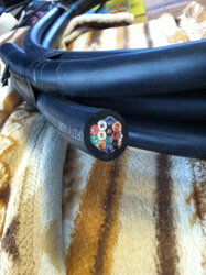
All new from the wall plug to a new panel, then a 16/12 multi conductor cable to the stove.
New timer, all new switches, multiple fuses with each component having it's own fuse to protect the system in case of a short in the auger or a fan.
A 3 position heat range switch connected through a set of 3 resistors to allow a low medium and high range setting that fits the need.
The low is 11 seconds, medium is 8 seconds and high is 6 seconds delay time.
The convection/comb blower is now on an adjustable triac with a broad range of speed.
The factory door switch was retained (Stops blower when door is opened)
Pressure switch was retained (shuts off auger when/if blower is off.
Safety snap switches were retained to maintain over temp/burn back protection.
Exhaust outlet booster fan is wired to come on as soon as main pwr is turned on, allowing easy starting without smoking in the room.
So far it's a great system, but I am toying with some mods to things to add a few more fail safes that were not even included in the late stoves.
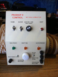
Here is a piccy of the panel while it was still under construction.
I added the text in Photoshop for effect.
Once I'm done totally, I will paint the panel to match the stove and get a local print shop to do a cool decal for the entire face.
I don't want to mess with things until I'm done hacking.
The panel mounts to the wall beside the stove. (This allowed far more room in the electrical spaces and to leave all the factory controls in the stove)
I discovered another relay company that makes superb components for the DIY'S
Not a tiny compact unit, but ROBUST and easy to fix in a pinch, also easy to diagnose.
Separate fuses and lamps tell wassssup in a jiffy.
Just sharing
Snowy
Some time ago, I revamped the controls to use an off the shelf timer and some other items in place of the original factory control board.
The reason being was to gain better control of the stove while operating on nut shells.
The factory feed settings were just way too far from reasonable
1- Was at 10 second feed intervals and was OK, but above that the feed rates were just into the ozones.
2- Jumped to 5 second intervals, and this was just right at the limits of a good Maximum rate
3,4 and 5 were waaaaaaaaaaaay too fast and totally unusable.
Other than myself at the controls, someone setting the feed above 1 was flirting with major issues.
The convection fan has a shunt tube connected to the fire pot to enhance air feed to the fire, and is controlled through a triac that is set in accordance with the feed rate.
The #1 feed rate has a very low fan speed with no provisions to change it other than the internal trimmer pot.
The next setting runs the fan a lot faster, and again it is just not to my liking.
The last year or so has seen things running with a batch of different controls, some of which were adaptations of the factory pieces, with a few items changed.
Sooooooooooooooo, "NUFF OF THAT"
Decided to do a start from scratch controller on this little critter.
I replaced all the factory parts, checked it out for function, then abandoned it in place, just disconnecting the wires and taping the connectors.
All new from the wall plug to a new panel, then a 16/12 multi conductor cable to the stove.
New timer, all new switches, multiple fuses with each component having it's own fuse to protect the system in case of a short in the auger or a fan.
A 3 position heat range switch connected through a set of 3 resistors to allow a low medium and high range setting that fits the need.
The low is 11 seconds, medium is 8 seconds and high is 6 seconds delay time.
The convection/comb blower is now on an adjustable triac with a broad range of speed.
The factory door switch was retained (Stops blower when door is opened)
Pressure switch was retained (shuts off auger when/if blower is off.
Safety snap switches were retained to maintain over temp/burn back protection.
Exhaust outlet booster fan is wired to come on as soon as main pwr is turned on, allowing easy starting without smoking in the room.
So far it's a great system, but I am toying with some mods to things to add a few more fail safes that were not even included in the late stoves.
Here is a piccy of the panel while it was still under construction.
I added the text in Photoshop for effect.
Once I'm done totally, I will paint the panel to match the stove and get a local print shop to do a cool decal for the entire face.
I don't want to mess with things until I'm done hacking.
The panel mounts to the wall beside the stove. (This allowed far more room in the electrical spaces and to leave all the factory controls in the stove)
I discovered another relay company that makes superb components for the DIY'S
Not a tiny compact unit, but ROBUST and easy to fix in a pinch, also easy to diagnose.
Separate fuses and lamps tell wassssup in a jiffy.
Just sharing
Snowy
Attachments
Last edited:

") Keep us posted on progress and testing!
Keep us posted on progress and testing!