It seems there isn't really a central place for people to post piping diagrams of their system.
As a new member working on an a wood gasser installation of my own (here), it would be great to look through a few.
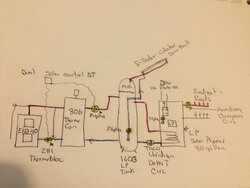
Plumbing schematics, pictures, or even rough drawn stick figures, anything that shows how the darn thing is piped. Not only would I find it helpful but others may have similar setups to one another which could start some good talks about performance/results.
Myself, I plan to go the Nofossil route, since it closely resemble what I have already set up, bit maybe there are others/variations...
As a new member working on an a wood gasser installation of my own (here), it would be great to look through a few.
Plumbing schematics, pictures, or even rough drawn stick figures, anything that shows how the darn thing is piped. Not only would I find it helpful but others may have similar setups to one another which could start some good talks about performance/results.
Myself, I plan to go the Nofossil route, since it closely resemble what I have already set up, bit maybe there are others/variations...
Last edited:


")