whitfield profile 20 problem

  • Active since 1995, Hearth.com is THE place on the internet for free information and advice about wood stoves, pellet stoves and other energy saving equipment.

    We strive to provide opinions, articles, discussions and history related to Hearth Products and in a more general sense, energy issues.

    We promote the EFFICIENT, RESPONSIBLE, CLEAN and SAFE use of all fuels, whether renewable or fossil.
Status
Not open for further replies.
I've tried reaching that guy David in Ontario, He doesn't respond to my e-mails so I'm not sure he's still doing these board repairs, any insight would be appreciated.

David has several e-mailaddresses and he's also on Skype as you can see here. He could be very busy, though.
But give these options another try:
PCB Repair, David in Canada.jpg


if you look close at this picture there's 4 holes on the right, they seem to be a female insert so possibly made for a calibration sensor of some sort,

These 4 holes are test ports for the voltages specified by the text next to them. A very handy feature, when troubleshooting. My Quest Plus also has them, but the finetrim is a more "old fashioned" trimpot version.
With a voltmeter or an oscilloscope you can monitor, if the voltages fed to the blowers and auger motor are correct. CAUTION: These voltages can be lethal, so do take care. If you don't have enough experience with this, please let someone more experienced help you.

As I understand your issue, you have an unstable pellet feed, right? Now, this could be either due to wrong auger timing or an unstable output voltage from the Triac on the control board, so let us focus on the auger voltage... on this video I'm monitoring the auger voltage on my Quest Plus by connecting a scope to the test ports marked: Common and Auger. A healthy voltage should be perfectly symmetrical and at full line voltage and this is clearly the case here. Note: I'm using a 10:1 divider probe to protect the scope input. It can max. handle 80 Volts peak-peak. The line voltage is 230 V, 50 Hz here.
Also, we can monitor the timing and by watching the time counter on Youtube, it is easy to see that the timing is up to specs on my stove.
Lucas, with a voltmeter you should be able to make the same test of your auger voltage. ( except testing for symmetrical waveform, this requires a scope ).

Monitoring the auger voltage on my Whitfield Quest Plus:


I tried to do It like It was explained in my last post but It's not doing the fan change sound like described after the light goes on when i hit the calibration button I pressed cal again and nothing, I understand that this person doesn't have the same stove as I but I thought I would at least try,

As for the calibration procedure, I'm sure this is somewhat similar to setting the time and date on a digital clock. You know, by pressing a couple of buttons in a certain sequence, so with some trials I bet you'll soon get to know how the thing is "ticking". Remember to monitor the voltages through the test ports while altering the settings. This way you'll see any changes immediately.

The service manual will most likely have some exact information on the calibration procedure, but I only have the owners manual. The service manual can be purchased here: http://woodheatstoves.com/whitfield-profile-2030-service-manual-p-2159.html

Good luck and take care. Keep us posted

Bo
 
Last edited:
  • Like
Reactions: Bioburner
I also tried to get more answers from this tread but I can't access to It, can a moderator try to reach this person please to jump in my tread, thank you.


https://www.hearth.com/talk/threads/whitfield-profile-20-fuel-feed-trim.47814/
Short on time today ... if there is a member that you want to contact just click on their name in their avatar. A pop-up box will show up and click on start a conversation ... didn't take a close look at participants of that thread so not sure if they are active members.

Can try the search box for board repair. I know there are others who repair boards but mostly in the US...
Thank you
David has several e-mailaddresses and he's also on Skype as you can see here. He could be very busy, though.
But give these options another try:
View attachment 156624


These 4 holes are test ports for the voltages specified by the text below them. A very handy feature, when troubleshooting. My Quest Plus also has them, but the finetrim is a more "old fashioned" trimpot version.
With a voltmeter or an oscilloscope you can monitor, if the voltages fed to the blowers and auger motor are correct. CAUTION: These voltages can be lethal, so do take care. If you don't have enough experience with this, please let someone more experienced help you.

As I understand your issue, you have an unstable pellet feed, right? Now, this could be either due to wrong auger timing or an unstable output voltage from the Triac on the control board, so let us focus on the auger voltage... on this video I'm monitoring the auger voltage on my Quest Plus by connecting a scope to the test ports marked: Common and Auger. A healthy voltage should be perfectly symmetrical and at full line voltage and this is clearly the case here. Note: I'm using a 10:1 divider probe to protect the scope input. It can max. handle 80 Volts peak-peak. The line voltage is 230 V, 50 Hz here.
Also, we can monitor the timing and by watching the time counter on Youtube, it is easy to see that the timing is up to specs on my stove.
Lucas, with a voltmeter you should be able to make the same test of your auger voltage. ( except testing for symmetrical waveform, this requires a scope ).

Monitoring the auger voltage on my Whitfield Quest Plus:


As for the calibration procedure, I'm sure this is somewhat similar to setting the time and date on a digital clock. You know, by pressing a couple of buttons in a certain sequence, so with some trials I bet you'll soon get to know how the thing is "ticking". Remember to monitor the voltages through the test ports while altering the settings. This way you'll see any changes immediately.

The service manual will most likely have some exact information on the calibration procedure, but I only have the owners manual. The service manual can be purchased here: http://woodheatstoves.com/whitfield-profile-2030-service-manual-p-2159.html

Good luck and take care. Keep us posted

Bo

Thanks Bo, I appreciate this, I've downloaded the service manual and It explains exactly how to proceed with calibration for this unit, I'll try this on the week-end, cheers.

Lucas
 
  • Like
Reactions: Lake Girl
I also tried to get more answers from this tread but I can't access to It, can a moderator try to reach this person please to jump in my tread, thank you.


https://www.hearth.com/talk/threads/whitfield-profile-20-fuel-feed-trim.47814/
I tried to follow this exact procedure to calibrate my stove but It doesn't go to the next step for combustion calibration when i push the button twice so I guess my next step is to have the controller checked out. when i tested with the volt meter I'm getting exactly what is going on, at low a very high voltage etc.

Lucas

Fuel Feed Trim Steps: Rev C
1. Push button “once” to access fuel feed calibration
mode.
2. Identify the current calibration setting indicated by
one RED LED bar and the word “AUGER” in red
below heat control button
3. Push the “HEAT” control button to adjust setting
UP. Each push raises the RED LED bar and
increases feed rate.
4. Push the “BLOWER” control button to adjust
setting DOWN. Each push will drop the RED LED
bar decreasing feed rate.
5. Push the calibration button two more times to lock
in selected setting.

Combustion Voltage Trim Steps: Rev C
1. Push button ‘twice” for access voltage calibration
mode.
2. Identify the current calibration setting indicated by
one YELLOW LED bar.
3. Push the “HEAT” control button to adjust setting
UP. Each push raises the YELLOW LED bar &
increases voltage 5%.
4. Push the “BLOWER” control button to adjust
setting DOWN. Each push lowers YELLOW LED
bar decreasing voltage 5%.
5. Push the calibration button once to lock in
selected results.
 
  • Like
Reactions: tunamastr
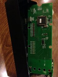
Since you get no response at all when pressing the calibration button, the first thing to suspect is the tactile switch on the circuit board. These tactile switches are prone to fail in this way. I have seen this error many times before on various types of equipment.
I found a picture of an opened profile 20 control board ( or is it a Profile 30? ) to help you locate the switch on the circuit board.
Profile20-2 IMG_2091.JPG

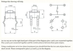
With an ohmmeter it is easy to determine if the switch needs to be replaced. Here's some useful info on how to test a tactile switch for correct functionality.

Tactile switch.jpg

As you can see on the diagram above the switch is normally open ( infinite Ohms ) when measuring Ohm between pins 1,3 or pins 2,4. Pressing the button while having the ohmmeter test pins connected to either pins 1,3 or pins 2,4 should result in a zero Ohm reading immediately!
If the tactile switch tests ok, I'm afraid something is faulty deeper inside the electronics and you'll need to send the board to David for repair.
Keeping my fingers crossed that it's only the tact switch, though.

Good luck and keep us posted.
Bo
 
Last edited:
Status
Not open for further replies.