we all like graphs

  • Active since 1995, Hearth.com is THE place on the internet for free information and advice about wood stoves, pellet stoves and other energy saving equipment.

    We strive to provide opinions, articles, discussions and history related to Hearth Products and in a more general sense, energy issues.

    We promote the EFFICIENT, RESPONSIBLE, CLEAN and SAFE use of all fuels, whether renewable or fossil.
Status
Not open for further replies.

TCaldwell

Minister of Fire
FullSizeRender.jpg
FullSizeRender_1.jpg
FullSizeRender_2.jpg
FullSizeRender_3.jpg
FullSizeRender_4.jpg
FullSizeRender.jpg
FullSizeRender_1.jpg
FullSizeRender_2.jpg
FullSizeRender_3.jpg
FullSizeRender_4.jpg
FullSizeRender.jpg
FullSizeRender_1.jpg
FullSizeRender_2.jpg
FullSizeRender_3.jpg
FullSizeRender_4.jpg
FullSizeRender.jpg
FullSizeRender_1.jpg
FullSizeRender_2.jpg
FullSizeRender_3.jpg
FullSizeRender_4.jpg
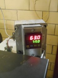
some recent trend charts of start of burn and mid burn, the red line is controller output that starts at 10% [secondary air damper], the primary op is 100 minus the secondary op, in this case 90% open. Basically this is a reverse acting process with the secondary damper switched to reverse acting and the primary to direct acting.
These trends represent a gain scheduling approach to o2 control, the pid first set's range is from 20.9% o2 to 7% o2, with proportional band =25, integral =4min,30sec, derivative=2.5sec. The early starting controller output allows a gentle descent to the 7% switch point. From there the second pid set takes over proportional band=28, integral=22.5sec and derivative at 1sec, the operating setpoint is 5%o2 [the flat orange line at 5%]. The second pid set is relatively aggressive at holding the process value [blue line] close to the sp, with pretty dependable disturbance control.
This is a pretty simple strategy that seems to work well for o2 control, one single input, o2/ one output to dampers. I have not tried gain scheduling using temp instead of o2 but it should have some degree of success.
 
Last edited:
  • Like
Reactions: BoilerMan
sorry, They are pics off a iphone, pc loads them a zipp file on hearth, I have to wait for my daughter to locate the iTunes download cord and load as pics unless you know another way
 
What is the input from? TC? And what exactly are you controlling with the PID, damper motor?
 
The input is a 4-20mA signal from a fluegas analyzer representing residual o2 in the flue, after the combustion process. The pid controller calculates a output from 0-100 pct that controlls the 2 belimo damper actuators. One damper Controlls the primary air the other secondary air.
 
Cool! I'm going to resist the temptation to get into a graph war, though.

I've been meaning to add a lambda sensor to mine for a very long time now - I even have the sensor. Somehow, I've just been too busy :-(

Still, I've done a bunch of PID control loops in my system and in customer systems. I love seeing a system performing at its best, and TC's is impressive.
 
A graph war you got it hands down!, You know I've been fooling with this for too long, but this gain scheduling is actually pretty consistent, at least with o2. The key seems to get control action early in the o2 descent from 20.9 to what ever your setpoint would be, basically when your process value gets near the setpoint, one some stability like a plane's approach to a runway and two, that the dampers are already at a output that they are in control, not trying to play catchup on a large error. The tuning constants for the descent would cause large slow oscillations if they were used to try to hold a setpoint, the pid set used at setpoint would force too fast of a descent at the start of burn. Typically the primary damper's output is about 33-35% and the secondary 65-67%, for the shape of a round damper those positions are in a good spot to control from. Also if you trend combustion temp, this gain schedule result shows a controlled steady increase and a leveling out, without large negative swings associated with o2 undershoot on the initial o2 descent from 20.9 to setpoint. The large controller output below setpoint will actually start to put the fire out with secondary air, lowering combustion temps 100-200 degf. After that it takes a while to stabilize, but with early control action this is avoided
 
Perfect. Simple and effective. I would have used something like that, except for three problems:
  1. I want to datalog the PID output
  2. I sometimes need to change the control setpoint over the course of a fire
  3. I have a pathological need for complexity and control. Simple and effective just doesn't cut it ;-)
 
  • Like
Reactions: brenndatomu
.... I've been fooling with this for too long.....
If I ever get around to installing my lambda sensor, I'd like to pick your brain a bit on tuning it. I'm thinking two variable speed blowers (primary and secondary), while monitoring combustion temperature and O2 (and maybe inferring where I'm at in the burn).

Do you do anything to protect your lambda sensor during startup when there's nasty smoke?
 
The lambda sensor is pretty robust, about once a week i hit it with compressed air. The only real need for that is because the impacted flyash tends to dampen the signal, like adding a filter time constant. The two blowers I believe would give better control, sort of like fuel injection rather than a carb. The only thing keeps me from wanting to try that would be the pressureized firebox, reload could be a bit smokey as the path of least resistance would be opening the loading door. I have tried a few different controllers that had math functions, combining o2 and temp into one output, trying to steady or control with the influence of temperature but neither of these controllers had the ability to form a equation. I control my inducer speed with temp pid, The overall airflow through my boiler is very nonlinear, I start the burn at 60hz=3600rpm, once above 1250deg it drops to 3550rpm, this small rpm reduction lowers the cfm enough if the wood is very dry to keep the overall burn easily controllable. Also what helps is to clip your high and low controller outputs, 10%min-85%max. In 4 years, I am on my 2nd sensor.
 
Another approach I've had good luck with is cascade control, temp is the master and o2 is the slave, not extremely precise but very stable. For this to work the slave time constant should be at no more than 1/4 of the master time constant, they create one output. There are some very progressive pid developmental platforms such as microstar labs, c++ and rex controls, no coding required, it can interface your inputs and outputs through a inexpensive plc and control through a raspberry pi with their software through your pc, under 500$. Rex has some you tube vids as well.
 
Another approach I've had good luck with is cascade control....

I've got a reasonable amount of spare CPU capacity in the Vesta. The PID algorithm I'm using now is pretty simple. I'll be looking at some more sophisticated techniques, as I already have the hardware in place.
 
Status
Not open for further replies.