how to enlarge header (carpentry)

  • Active since 1995, Hearth.com is THE place on the internet for free information and advice about wood stoves, pellet stoves and other energy saving equipment.

    We strive to provide opinions, articles, discussions and history related to Hearth Products and in a more general sense, energy issues.

    We promote the EFFICIENT, RESPONSIBLE, CLEAN and SAFE use of all fuels, whether renewable or fossil.
Status
Not open for further replies.

RustyShackleford

Minister of Fire
Jan 6, 2009
1,344
NC
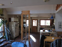
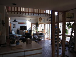
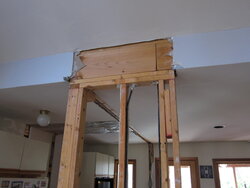
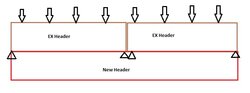
House remodeling. I need to enlarge (from 7 to 10-12 ft) and shift (about 5ft sideways) an existing header where one passes between rooms. On one side, the header has 2x8 ceiling joists nailed to its face; cathedral ceiling 2x12 rafters, on the other side, are nailed to the top of it. The existing header is a flitch beam, steel sandwiched between two 2x10s. I have computed (pretty conservatively) the load on the new header at about 900 pounds per linear foot (total) and about 575 plf of live load. There are several ways to proceed, and I can't decide among:

1. Sister a 2x10 piece of LVL (engineered wood) to the exposed face (the cathedral side) of the existing header. Unfortunately, the original carpentry was a little sloppy, and the existing header isn't directly on top of the girder which supports the floor which supports the wall with the header). Unfortunately, it's off to the side of the face where I'd add the LVL, so it'd be unacceptably off center after I did that.

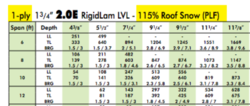
2. Rip out the existing header and replace it with a 2-ply LVL beam (3.5" x 9.5"). This is "best" in the sense it's very strong (so can make the opening 12ft wide instead of 10ft). But a gigantic PITA: have to build temporary supporting walls on both sides of existing header, sawzall the thing out of there, etc. Oh, did I mention that almost every piece of Romex in the house runs right along the edge of this header ? At least I can do my own electrical work ...

3. Like #2, except after all the sheetrock is off, try to remove the flitch plate from the existing header, and the 1/2" plywood from the part that wasn't formerly over the opening, and then insert a new fitch plate of the proper length. Probably a non-starter too, especially if they used glue when they built the original flitch beam.

4. Put some sort of piece of structural steel under the existing header. I'm currently favoring this option. Not sure what to use - angle, square tube, channel ? Strength shouldn't be an issue. Deflection definitely is - there's no framing or door, but there is sheetrock; I've been told up to 1/2" might be ok. That means I need a section with a moment of inertia of about 10 in^4 (if I'm computing correctly).

Thoughts on what I should do ? Thanks !
 
Last edited:
Following up on the idea of using structural steel under the existing header, I have a few questions for those knowledgable on ME ...

The formula for maximum deflection (at center) of a uniformly loaded beam is apparently:

(5/384) * W * L^3 / (E * I)

... where W is total weight in pounds, L is length in inches, E is modulus of elasticity (29*10^6 for mild steel), and I is the moment of inertia for the cross-section of the beam. However, at least one site I found replaces the 5/384 factor with 1/192; am I missing something ?

This site (http://www.engineersedge.com/standard_material/Steel_angle_properties.htm) has "I" for a 5x5 1/2" angle iron (a likely suspect for my application) at 11.3. However, this site (http://www.engineeringtoolbox.com/area-moment-inertia-d_1328.html) shows "I" for a rectangular cross section computed as B * H^3 / 12. It looks to me like giving that 5x5 piece of angle iron a value of 11.3 assumes both faces of it are resisting bending as though they were oriented vertically - which of course they aren't. One face resists bending, the other only resists buckling (it resists bending slightly, but far less so than the other face).
 
i'm a structural engineer.

i would personally opt for option 2, even if it's more work. at least with that solution, you can rest comfortably knowing that what you did will work as you assume it will.

with the other options (sistering, adding steel), you run into issues of the connection strength of the fasteners (presumably nails or lag bolts, respectively). any time you try to make a composite structural member, all the fasteners need to be checked to handle the resulting shear forces in them. for example, if you took ten 2x4s and stacked them up to make a 15"x4, that is not the same strength or stiffness as a single piece of timber measuring 15"x4. it would be, however, the same if you were able to use fasteners/glue/etc to transfer the shear between the 2x4 pieces. make sense?

so, same thing happens when you try to sister a beam together. for a header, especially with the change of length you're talking about, this is a real concern. the maximum stress in your 12ft long future header is at the 6ft point (center of header). that's about 1ft away from where your sistering would start. so, very big loads on the fasteners. it can be done, but it would be best not to.

for the supplemental steel piece, sure, and angle could work. i'd get the deepest, thickest angle you can find with an appropriate flange width for underneath your current header. so, maybe an L8x4x1? keep in mind, single angles like to bend funny, so you'd need to bolt the crap out of it to prevent lateral torsional buckling. alternatively, you could use an HSS directly below your header (HSS = tube steel). you could probably get away with an HSS 5x5x1/2 or HSS 6x3x1/2 from a strength standpoint assuming your loads are 1500PLF and your span is 12ft. i'd need to double check the deflection for you (L/360 as the limit), but we can work on that once you give me your space constraints. in general, if it works from a strength standpoint, it works from a deflection standpoint.

regarding your deflection criteria, 5/384 should be correct for a uniformly loaded beam. 1/192 is for a point loaded beam with the point load at the center of the beam.

draw up a sketch and allowable sizes you want to work with and i can look into it.
 
  • Like
Reactions: vinny11950

Wow, thank you so much.

I agree option #2 is the best, in the sense of being the "right thing", but man, it's gonna be a pain; I'll chat with my carpenter buddy and see just how big a pain.

I hear you on the fasteners. One thing though (maybe I used the word "sistering" wrong), the LVL I was thinking of fastening to the face of the existing header would span the entire length, not just part of it. One big issue, I know one of the existing 2x10s has a break over the new opening, but does the other ? I'm about to do some sheetrock demolition and find out ! And the issue the expanded width would hang off the subfloor girder even farther than it already does. Although maybe I could fasten something to that girder to widen it in the right direction; only needs to be done in the few feet when the two point loads come down, maybe just little pieces of angle lagged to the existing girder in between the floor joists.

I like the relative ease of the steel scheme. By HSS you mean hollow tubing with a rectangular cross-section ? The clearance is now 8ft, so I can fit a pretty big piece and still have 7'6" headroom, fine by me. Gonna be heavy. And I still probably need temporary support walls (would need with the angle-iron too); but not nearly as painful as actually removing the old header.

regarding your deflection criteria, 5/384 should be correct for a uniformly loaded beam. 1/192 is for a point loaded beam with the point load at the center of the beam.
Deeply confused. Why would having the whole load at the center of the beam cause less deflection (1/192 multiplier instead of 5/384) ? I see a 1/48 multiplier at wiki article; what factor of 4 am I missing ?

draw up a sketch and allowable sizes you want to work with and i can look into it.
Great, thank you. I will try to get that done over the next 24hrs or so - gotta go destroy some drywall now !!
 
Last edited:
Can you address my question of why it seems to be like the table overstates the moment of inertia of angle iron by a factor or two (because I think the same issue comes up for square tube). Let me explain my reasoning:

Let's take 6x6x1 angle, for simplicity. Table linked in OP says 35.5 in^4. But I figure only one of the two faces is resisting a typical bending load (e.g. the one oriented vertically, supporting my beam). So it's not much stronger than a 6x1 piece of plate, which is 18 in^4 (using B * H^3 / 12). The horizontal face only gives you 0.5 in^4; of course it's very important since it resists buckling, which is important for my header, but I can't see how it doubles that 18 in^4 figure to 36 in^4.
 
it's hard for me to accurately picture what issues/conflicts you have going on. post some pics :)

HSS = hollow structural steel. can be a round pipe, or rectangular or square tube. there are many sizes/options that could work for you. so could a W-section (I-beam), but i think the HSS should be easier to work with.

for the deflection issue, take a look here for various loading diagrams (edit: i guess i looked at the wrong deflection chart earlier; your 1/48 is correct for a point load on a SIMPLY supported structure --- my 1/192 was for a FIXED FIXED structure):
http://www.awc.org/pdf/codes-standards/publications/design-aids/AWC-DA6-BeamFormulas-0710.pdf
keep in mind that when there is a point load at the center of a beam, you're using "P" in the deflection equation. in the uniform load case, you're using "w", which is a uniform load. so, it's an apples to oranges comparison in terms of load, so you have a different multiplier ratio (5/384, 1/192, 1/48, etc). example (ignoring E and I, since those are the same for both cases):

1000lb point load, centered on 10ft span, deflection = [1 kip * (10ft * 12"/ft) ^ 3 ] / 48EI = 36000 / EI

100 lbs/ft uniform load, 10ft span, deflection = [5 * (0.1100/12) * (10 * 12"/ft) ^4 ] / 384EI = 22500 / EI

^ both cases have the same total load (1000lbs), but because of the distribution of the loads, you deflection changes.

without looking at the link for the 6x6x1 angle, here's what's going on: strength and stiffness of members is greatly affected by where the material is located. this is why I-beams are used in many high rise buildings - they have the most material far away from the centroid of the section. this is why standing on a 2x4 in a flat position is flexible, but when you rotate it so it's upright it's way stiffer (5+ times stiffer). same thing happens for your angle. even though that horizontal flange is flimsy and weak all by itself, the reality is that it's welded/cast monolithically to the vertical part of the angle. when that happens, you start to get a distance multiplier effect taken from the centroid of the angle to the centroid of the horizontal flange. the distance multiplier is a squared number, so the effects are profound.

i didn't watch this video, but it has a good rating so i assume it's correct:
 
it's hard for me to accurately picture what issues/conflicts you have going on. post some pics :)

your 1/48 is correct for a point load on a SIMPLY supported structure --- my 1/192 was for a FIXED FIXED structure):
Sorry, I am also an engineer - but electrical, not structural or mechanical - so all this stuff is new to me and I really want to understand. Right now I need to understand the difference between a "simple" beam and a "fixed" one; I guess it has something to do with the way the ends are fastened, maybe how shear is controlled ?

Anyhow, that is neither here nor there, for now. So here are some photos. The first looks from the living area into the kitchen. You can see the existing opening - the old left side support has drywall removed. I will build a new left-side support that comes out 2ft from the side wall of the house (where the refrigerator sits). Right-side support will be by extending the wall you see on the right (near the hanging blue lamp). It's now 14.5ft from the left side of house to where that right-side wall is now. New left-side wall will take up 2ft. That leaves 12.5ft open. So I will extend the right-side wall 1.5-2.5ft, depending on whether the new header can be engineered to support a 10ft or 11ft wide opening. The kitchen rafters, which butt into the back face of the header, are 12ft long 2x8s, ceiling is 1/2" drywall.

Second photo looks from the kitchen into the living area (ignore the catwalk). The living area is 26ft wide, and the header will support one side of its 10/12 gable roof. It's framed with 2x12s (so they're 17ft long), which bear on top of the header. It's decked with 1/2" OSB, and roofed with 26ga galvalume. Note also there are collar ties on the ceiling, creating a flat ceiling in the middle of the cathedral (you can't see in photo). The cathedral ceiling is 1/2" drywall on the slanted sides, and 3/4" T&G pine in the center.

Attic over the kitchen is unfinished, may be used for light storage in the future. Attic over center of cathedral is also unfinished and very unlikely to ever be used for storage.

Third photo shows detail of existing header where I pulled drywall off yesterday. Note break in 2x10; this means both 2x10s will have discontinuities over the new opening.

Fourth photo shows roof from outside, so you can see how 5/12 gable over kitchen partially rests on cathedral roof's rafters.

I've also shown the spreadsheet where I computed the load on the new beam in pounds per lineal foot. The amount of side gable supported by the big gable is a triangle about 16ft long (length of side gable rafters) and 5ft wide (the amount of its ridge that extends over the big gable) - so hypotenuse is the roof valley. So I compute it's entire area load and then divide it by the beam length to get its contribution to the PLF on the beam (that's the only place the beam length is used in these calculations). This is probably pretty pessimistic on the snow load, since snow cannot fall on the portion of the cathedral roof overlapped by the kitchen gable.
 

Attachments

  • IMG_0002.JPG
    IMG_0002.JPG
    142.4 KB · Views: 505
  • IMG_0003.JPG
    IMG_0003.JPG
    150 KB · Views: 331
  • IMG_0004.JPG
    IMG_0004.JPG
    92.9 KB · Views: 999
  • kitchen beam.pdf
    25.9 KB · Views: 255
  • IMG_0005.JPG
    IMG_0005.JPG
    292.3 KB · Views: 387
Last edited:
As far as how to proceed, I think options 2 and 4 (in my OP) are only viable ones. Number 3 is probably a fantasy, and option 1 is probably ruled out by the recent finding that neither of the existing 2x10s is solid across the new header opening (so only the sistered piece of LVL would be continuous). Though I suppose I stand a chance if I use a 11-7/8" deep piece of LVL (see attached loading table for the line my lumberyard stocks). But there's the fastener issue you mention, plus the thing becomes even less centered on the girder (below the subfloor); not good.

For option 2, I've got it made in the shade, even for an 11ft opening. Made it the shade engineering-wise. Then the real fun begins - ripping out the old beam.

So that leaves option 4. I hear you on the angle bending weird. Seems like rectangular cross-section HSS is the way to go ? So how much center deflection is ok ? And, maybe, can the beam be designed to be "fixed" instead of "simple" (so 1/384 multiplier instead of 5/384, if I read your link correctly for fixed-fixed with uniform load) ? I understand this moves moments from the center to the ends, so may stress connections (or make the design process too complex). But with bolts running through the top plates of the support walls, through the HSS, and into the existing header, it seems like fixed might fly.

Anyhow, Iron, I'm getting ahead of myself. I'm eager to see what you think, and hope I've given you enough information. Thanks again.
 

Attachments

  • Screen Shot 2016-02-06 at 4.29.55 PM.png
    Screen Shot 2016-02-06 at 4.29.55 PM.png
    27.9 KB · Views: 712
fixed vs. simple: you're almost certainly going to be in a simple end support condition. developing a fixed connection is a full penetration weld and sometimes has gusset plates. your sister studs to support a new supplemental steel header would need to be steel and would need to be welded with mitered corners, full pen welds. not worth it.

what are you going to do with the electrical wiring currently on the wall to be demo'd? it seems like that's going through the existing header???

i think option 2 is your best bet. option 4 would fundamentally be the same as option 2 (you need to fully support both roofs in order to cut out the old wall and put a steel beam UNDER the current header). if you were to do option 4, your deflection calculation would be slightly different than the equations you've been looking at because of how the wood header would effectively land on the steel header. we can cross that bridge later...

but, i think putting in temp walls wouldn't be too big of a PITA. the trick is always how to slide the new beam in between the temp walls. i would probably do it this way:
1. build 1 temp wall
2. place new LVL header next to temp wall
3. build other temp wall (sandwiching your new header
4. demo walls and ex header
5. lift header up into place, temporarily support using temp walls (2x running perpendicular)
6. frame new walls to support header
7. demo temp walls

make sense? i think that's the way i'd do it.

my biggest concern is with the raftered construction. gotta be careful to make sure that horizontal spreading loads are handled when you demo the existing headers. who knows how frequently placed the collar ties are (every other rafter?). be sure to check that out before starting to hack away. i guess by doing option 4, you would alleviate some of the horizontal spreading concerns...
 
Iron, thanks for getting back to me so quick. PLEASE understand, in my comments below, I might appear to be challenging you some. Please don't take offense. It's just because I want to understand fully.
fixed vs. simple: you're almost certainly going to be in a simple end support condition.
Ok, I understand there's no way I can hope for a 1/384 multiplier. But even with 5/384, looks like 6x4x1/4 HSS has I = 22 in^4, about the same width as header and only lowers opening to 7'6" and will only add 16plf weight, and gives 1/4" deflection under live load (less than 1/2" under total load).
if you were to do option 4, your deflection calculation would be slightly different than the equations you've been looking at because of how the wood header would effectively land on the steel header. we can cross that bridge later...
Wouldn't the load still be uniform - even more uniform, not just a series of evenly-paced loads, as the header spreads out the loads from the rafters ? Seems like the main effect would be to fix the ends of the HSS more securely, since header rests on the ends of the HSS, especially with big lag bolts running all the way thru the top plate of supporting walls, the HSS, and into the old header ? Thus, wouldn't it be at least a little bit better than 5/384 ?
what are you going to do with the electrical wiring currently on the wall to be demo'd? it seems like that's going through the existing header???
I've got that covered - very comfortable will electric work. Will pull Romex up into attic for now, then probably put those same switches in new support wall that's to the right (in first photo).
i think option 2 is your best bet. option 4 would fundamentally be the same as option 2 (you need to fully support both roofs in order to cut out the old wall and put a steel beam UNDER the current header).
Oh yeah, for sure building the temp walls needs to be done for both. But I'm more dreading the process of having to disconnect the old header from probably about 10 rafters plus 10 ceiling joists. Thanks for the blow-by-blow; roughly my thinking, plus, great idea for positioning the new LVL before building 2nd temp wall.
my biggest concern is with the raftered construction. gotta be careful to make sure that horizontal spreading loads are handled when you demo the existing headers. who knows how frequently placed the collar ties are (every other rafter?). be sure to check that out before starting to hack away. i guess by doing option 4, you would alleviate some of the horizontal spreading concerns...
Talking to carpentry buddy, seems like the temp wall on cathedral side is nailed through the sheetrock to every rafter, but I guess that doesn't help with spreading (unless that wall is angled away from the header and fixed to the floor, which would be tough since the floor is brick). But yes, there are collar ties on every rafter; but they are pretty high up (less than 1/3 of the way down the cathedral from ridge to headers). It's mighty worrisome to me, now you point it out. In fact, this is making me lean rather strongly towards HSS option. Can you say more about your reservations about it ?

EDIT: Another option, which avoids the hassle and spreading loads associated with removal of the existing header, and also avoids having to design steel, would be to add a beam below the existing header, made from either 2 plys of 9-1/4 or 9-1/2 LVL, or a flitch beam made with 5-1/2 or 7-1/4 LVL and 3/8" or 1/2" steel.
 
Last edited:
1. keep in mind using the HSS would require furring strips to allow you to drywall. glued or boxed and screwed.

2. the load would still be uniform, BUT, the way in which the load transfers to your steel section would not be uniform because of how the existing wood headers will try to pivot. since you have a splice/butt joint in the ex header, they will begin to sag there. so, i would assume that the tributary load on the ex header splits 50% at the splice and 50% at the other end. you can also analyze it as uniformly distributed. i would look at both cases and pick the governing case to size the HSS. if you think an HSS 6x4x1/4 works, then you could always increase the wall thickness to 3/8 and cover any oversights. a little extra $ on material will buy a decent amount of stiffness/strength/peace of mind.

4. to disconnect the header from the rafters (probably toenailed), i would recommend using an oscillating tool with a carbide blade. should make quick work of separating the nail from the wood. if you just try to pry the header off, you'll be in a world of hurt. make sure to cut into the ex header, not into the rafter. should be about 1 minute per nail.

5. biggest drawback to HSS method is loss of ceiling height there. but yeah, it's starting to seem like that's the better choice overall. if you get an HSS from a local shop, see if they can put a camber in it. calculate your anticipated dead load deflection and have them camber it to that amount. if you do this, that will mean you need to jack up your ex header a bit to fit the HSS in place. but, when the HSS is installed, the dead load will zero out the camber and you won't have a sag in the beam. whether this is important to you is your call. jacking obviously has it's drawbacks.

6 (EDIT). i am not sure what you're picturing here. would the new beams go in the same spot as the HSS theoretically would go? i've not worked with flitch beams before. seems like it's kind of a dicey method to rely on both the strength of the wood and steel since steel is stiffer (per unit measured) and will therefore pick up most/all of the load right away, while the wood just goes along for the ride until it flexes enough to resist bending. the wood would, however, provide lateral stability for the steel.
 
keep in mind using the HSS would require furring strips to allow you to drywall. glued or boxed and screwed.
Could I simply glue the drywall to the HSS (and avoid furring strips) ? I could also just paint the HSS - the same beautiful Delft blue enamel as the nearby spiral staircase (coming down off that catwalk).
i would assume that the tributary load on the ex header splits 50% at the splice and 50% at the other end. you can also analyze it as uniformly distributed. i would look at both cases and pick the governing case to size the HSS. if you think an HSS 6x4x1/4 works, then you could always increase the wall thickness to 3/8 and cover any oversights.
Not sure I follow. You mean take the total load, split it so half is on one side of the splice and half on the other ? Could I worst-case it by figuring the PLF on the shorter side, then assume that's the PLF on the whole thing ? However, it turns out the splice is very near (within 1ft) of the mid-point of the new opening.
biggest drawback to HSS method is loss of ceiling height there. but yeah, it's starting to seem like that's the better choice overall

i am not sure what you're picturing here. would the new beams go in the same spot as the HSS theoretically would go? i've not worked with flitch beams before
I'm really starting to feel bad about removing the ex header, because of the issue of spreading loads; seems like asking for trouble.

Yes, I picture the LVL going below the un-removed ex header, same spot as HSS might go.

Ceiling height is not an issue, I believe; it is now 8ft, so I'm dropping it (at most, using LVL) to 7'2" or so, right where you pass through opening. Code here specs 7ft minimum ceiling height, and beam may drop 6" below that. So only issue is aesthetic, or if an NBA center comes to visit.

Forget my flitch beam comment: all it could do is save me 2-4" on how far that beam drops below the 8ft ceiling (versus using 5-1/2 or 7-1/4 LVL). The 9-1/4" LVL can easily carry the load, without any steel (see table linked in post #8).

Other reasons I'm leaning towards LVL instead of HSS: cost and ease of sourcing - the HSS will probably cost $200 or so (not that that's a lot of money, given this project) and the LVL can come from a lumberyard 10 minutes from me. Also, the HSS will weigh 200+ lb, will be a bit of a pain to install. Only advantage over the LVL is the ceiling drops 6" instead of 9-1/4" at the opening (and the penalty is less than that if furring strips are required).

Honestly, I'm leaning very strongly towards installing a 2-ply 9-1/4" LVL beam below the un-disturbed ex header. Do you think I should still be considering HSS or removal of the ex header ?
 
Last edited:
seems like going with LVL is the way to go for you.
I'm a little anxious about the fact I'll end up with a header (existing one plus new LVL) that's about 20" high. I just need to make sure it can't bend in the joint between existing and LVL. Existing is pretty well stabilized by joists/rafter coming in from opposite sides, I believe. Just need to restrict any tendency of LVL to rotate about its longitudinal axis. I figure I can screw the king studs into each end of the LVL, and then use some kind of braces (on the kitchen side) to lock existing and LVL together (probably just multiple 18" pieces of 2x4 attached to the faces of the two members, they'll just make the beam that sticks down at the edge of the kitchen ceiling 1-1/2" wider).
 
assuming the LVL are screwed nicely to the king studs, and those kings are well tied into your existing walls, i think you'll be fine with that part.

i think the lateral loads at this location must already be more or less balanced out since the wall your header currently sits on clearly has limited lateral capacity. so, just putting some PL between new and ex headers might be plenty to tie them together. i would recommend plywood instead of 2x4s to make a connection if you want to overkill it. 1/4" piece on each face of the header - glued and screwed.

likewise, with your king studs-to-LVL connection, you could always build your new walls such that that have 1/4" plywood under the drywall. this plywood would sandwich the ends of the LVL. or, if you don't care about width, you could use heavier plywood...
 
I spoke to the carpenter who helps me (intelligent, skillful, experienced). He likes this LVL under existing header plan, even thinks the 9-1/4" "bump" at the edge of the kitchen ceiling is a "feature", serving to visually delineate the two rooms. He feels we can easily lick the issue of locking the two headers together, and your plywood suggestions sound perfect.

I'm still a bit confused about the splice in the existing header causing a non-uniform load on the LVL (your point 2 in post #11). Are you saying that even with the splice near the center of the new opening, there will be more load on the center of the LVL, because of pivoting action of the two sections of existing header ? Can you give me hints/pointers how to analyze this ?

But I think this problem is basically solved. Thanks very much for your help !
 
Last edited:
do 2 checks:
1. wL^2/ 8 (uniform load)
2. PL/4, where P = wL/2

essentially, since the ex headers are short, they are much stiffer than the new header. as a result, when they bend, they MAY try to act like simply supported beams supported at their ends. if this is the case, you would get a point load reaction at the ends of each ex header that transfers into the new beam. probably overanalyzing, but it's ok to double check things like this. looking at both load cases should help you envelop the solution and pick the worst case.
I understand your explanation, but not the equations you gave. Basically, it sounds like each ex header has a point load reaction at each end that's half its load (so w/4, assuming the ex header splice is roughly in the middle, so each ex header's total load is w/2). The two w/4's, that are at the ends of the ex headers that are over the supports, can be ignored (as far as beam deflection). So basically I just need to analyze a beam that has a w/2 point load in the center (w/4 + w/4). Since the multiplier (for max deflection) is 5/384 for uniform load and 1/48 for load at center, but the latter is for only w/2, it seems like I'm actually better off with the half-sized load concentrated at the center.

Or maybe "load uniformly increasing to center" (Fig 6 in your link of beam formulae) is better. That has a multiplier of 1/60 instead of 5/384. So maybe de-rate loads by a factor of 60/(384/5) or 78%. But, as soon as you say that ex-header stiffness prevents the load on the LVL from being uniformly distributed, you also have to say that some of that load transfers to the ends of the ex headers that are over the supports. At least 22% of it.

Anyhow, like you say, probably overanalyzing. I'd be very surprised if a carpenter, using the LVL manufacturer's load table, thinks about this. I'd be even a little surprised if a local engineer, who I hired to do a quick calculation for me, would go this far.
 
Last edited:
Thanks. Looks like just what I said, no ? Half-sized point load at the center ?
 
Sigh. Looks like I'm back to option #1 or #2 (in my OP). Aesthetics apparently preclude putting a new beam underneath the existing header (because of the ceiling dropping down 6-9" at the edge of the kitchen).

I'm still terribly leery of excising the ex header (option #2), because of the issue of the big rafters spreading when they're temporarily dis-connected. Though I also trust my carpenter to get it right. Maybe brace the ridge beam to the collar ties, so it can't sag (since rafters are far less likely to spread if the ridge beam remains fixed) - and/or brace the temporary wall (that holds the rafters) with angles to the kitchen floor.

I realize option #1 could be done by sistering LVL to the kitchen side of the ex header. It still requires disconnecting (actually, cutting off 3-1/2" from) the kitchen joists; but the rafters would not need to be disconnected at all, which should make bracing against spread easier, nor would a temp wall be required on that side. This then actually centers the new composite beam better on the subfloor girder, than it was before.

As you point out: I now have to pay close attention to the fasteners between the ex header and the LVL. If I believe that half the big-gable contribution to the total load comes down as a point load on the LVL at the splice in the ex header, then we're saying each end of the ex header needs to be fastened to the LVL near the middle with fasteners that can handle a shear of about 2000lb (1/2 * 6ft * 700plf). That's a lot of lag screws, and may compromise the strength of the LVL too much.
 
tough to say. i recall using liquid nails in the past while building houses and having it pull right off (subfloor to joists) several days after applying. i doubt you could say that about epoxy.
 
Status
Not open for further replies.