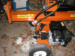
My Harbor Freight 30 ton splitter experience...

  • Active since 1995, Hearth.com is THE place on the internet for free information and advice about wood stoves, pellet stoves and other energy saving equipment.

    We strive to provide opinions, articles, discussions and history related to Hearth Products and in a more general sense, energy issues.

    We promote the EFFICIENT, RESPONSIBLE, CLEAN and SAFE use of all fuels, whether renewable or fossil.
Status
Not open for further replies.
Roxburyeric said:
Thanks for this great post as it has been very helpful in my consideration of purchasing a splitter. Here is what I have learned - Please don't take this the wrong way. Given the amount of travel time, work time, assembly time, upgrade costs, gas, time dealing with HF and down time from making the fixes and upgrades, it seems very clear to me that you could have bought a Timberwolf, Iron & Oak or other higher end unit from the start and most likely you would not have had to deal with all the issues you have described to us and you probably would have spent the same amount of money. Maybe I'm wrong and I do realize that some of your work wasn't needed - just wanted to make the unit better. Thanks

ABSOLUTELY WRONG!!! I've had less than one day of down-time, by the time I am finished with the current mods, it will be around two. These days were *chosen* deliberately because the weather outside was miserable and I wouldn't have been splitting anyway, thus no "real" downtime at all...

I had some leaks at first, most of which were easy enough to fix, and none of which were major. Even the valve (and now piston) leaks were minor enough that if the unit wasn't under warranty, I probably would have ignored them....

If I were just swapping out the valve (sent to me at no charge by HF, with no need to return the original - I may end up with a near complete set of spares for the hydraulics out of the deal) it would have been an hour or so of work. The mods I'm making are for my comfort, and can't really be charged against the machine for the most part, as they are in the same nature as hopping up a perfectly fine performing car - making it better than the original, not that the original was defective...

Even with the cost of the mods (which again shouldn't be charged against HF) I still am WAY under the cost of a comparable TSC unit, which I would have had to drive to pick up, instead of having it unloaded on my doorstep... (forget about the cost of an Iron Oak, or Timberwolf) If I'd bought one of the high-end units, I probably would STILL be making some of the mods I'm making today, which would still be costing me comparable amounts...

This splitter is not a purchase that I'm regretting.

Gooserider
 
Did some more fiddling with the splitter today, started off with a shopping trip - Turns out I misread the sign on the Hydraulic shop, closed today... :cry: So the high pressure line will have to wait until Monday or later.

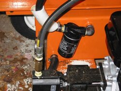
But I was able to get the return line fittings I needed at the local hardware store, and have re-positioned the return line filter, which gives the line just the perfect amount of slack.

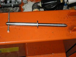
The other big project was to start making an easier to use locking pin for holding the beam in the up or down positions. The current pin is short enough that it's a bit of a struggle to get in and out of the holes. It's a 14mm nominal diameter, 0.55", so it's a little to sloppy for a 1/2" bolt. However I own a Smithy Mill/Lathe machine (a purchase I DO regret, but that's another story) that allows me to modify other parts as needed...

I started by picking up a 10" long, 5/8" diameter bolt, and chucking it in the lathe - then turning down a good length of it to about the same diameter as the original pin. I really should have used a 3/4" bolt, as I've still got a few signs of the threads showing, but it isn't bad. I put a bit more of a point on the end to make it easier to line up. Tommorrow (or sometime soon) I will braize a washer at the shoulder where I stopped turning to provide a stop, and drill holes for the hairpin clip and a "T" handle.

I didn't take any pictures of todays work, but I did download the camera and got some shots of yesterdays efforts....

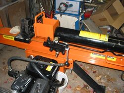
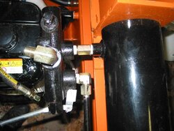
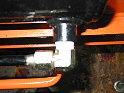
There are two shots of the old valve, showing the original position (without the high pressure and return hoses, which were sort of in the way) and the original connections to the cylinder, and the top cylinder connection.

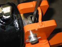
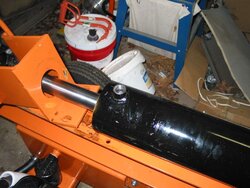
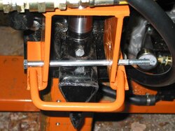
I decided that it would be easiest to work on the cylinder if I was able to get it so the ports were facing up, and I found that it was possible to lock it in place quite neatly by using the pin and a screwdriver to lock it into the mount in a non-standard position...

Gooserider
 

Attachments

  • old-hose-discon-2.jpg
    old-hose-discon-2.jpg
    64.1 KB · Views: 1,438
  • old-valve-cyl-connections.jpg
    old-valve-cyl-connections.jpg
    57 KB · Views: 940
  • cyl-top-fitting.jpg
    cyl-top-fitting.jpg
    47.7 KB · Views: 809
  • wedge-cyl-work-position.jpg
    wedge-cyl-work-position.jpg
    35.7 KB · Views: 817
More photos - The valve removed from the cylinder, also a look at the log ejector while it's disconnected.

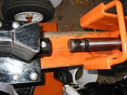
I separated the wedge and piston, as I didn't want to be turning the piston inside the cylinder w/o a reason (Those are linear motion seals, not rotary seals)

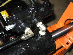
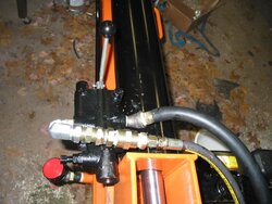
The connection on the new valve - notice the right angle fitting on the retract side... This was a real challenge to get on due to interference between the valve and cylinder. You have to put the fitting on the valve first, and turn it to just the right position so that you can screw the valve plus fitting onto the cylinder. Even so, I had to do some fun w/ elbows to get the return line fitting into place.

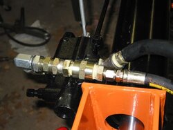
I also needed to make an additional bend and extend the plumbing on the HP line - this is a bit of a hack, and a darned expensive one, as those HP fittings cost a lot more than regular schedule 40 stuff. But it almost works... (I need about 1-2 more inches - will get that by adding a "TEE" and pressure guage at the pump end.)

You can also see the 45* elbow I needed to put on the low pressure return line to clear the cylinder.

Gooserider
 

Attachments

  • valve-remove-ejector-loose.jpg
    valve-remove-ejector-loose.jpg
    54.5 KB · Views: 813
  • wedge-piston-discon.jpg
    wedge-piston-discon.jpg
    55.5 KB · Views: 756
  • New-valve-on-cyl.jpg
    New-valve-on-cyl.jpg
    53.8 KB · Views: 751
  • new-valve-HP-hack.jpg
    new-valve-HP-hack.jpg
    40.3 KB · Views: 737
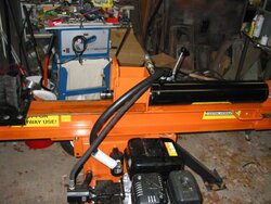
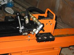
Finally, so you see the point of the entire exercise - the new valve is installed in the new position, some shots also show the new breather cap - though I need to do some more plumbing on this as it currently is blocking the lock pin holes.

Notice how the valve operating handle now sticks straight up (or back when in vertical mode) and is on the other side of the cylinder - much the way I prefer to work it.
 

Attachments

  • new-valve-installed.jpg
    new-valve-installed.jpg
    60.8 KB · Views: 785
  • new-valve-connected.jpg
    new-valve-connected.jpg
    55.4 KB · Views: 758
In this phase of improvements, I have just one or two other things I'd really like to fix. The cylinder on this machine has a 24" stroke, and is set up so that I have an effective 25" maximum log length... Since my target length is 18", with a maximum allowed length of 20", if I allow the auto-return detent to take the cylinder all the way up, I have to wait for about 5" of un-needed travel on every stroke - which takes a while (3-4 seconds). Doesn't sound like much but it adds up. I'd like it if the detent would kick out at around 20" or so, giving me two inches to get the log into position with, and cutting down on the wasted travel. At the same time I get the occasional over length log, which I'd rather go ahead and split while it's in my hands, and trim the rejects later... So I want something fast to switch back and forth.

I've seen mention the cylinder travel limiting collars that some folks have used, but those seem to me like they'd take to long to take on and off, plus I'm paranoid about damaging the chrome on the piston.

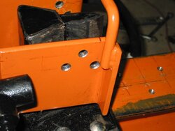
However there may be a very easy way to do it - The bottom cylinder support / log ejector on the HF splitter is a pretty substantial peice, and it sticks out about 3" further than the cylinder. (the wedge comes out to the end of it) If I were to drill a series of paired holes in the ejector and stick a pin (made from a 1/2" bolt) through them, the top side of the wedge would hit the bolt and trip the detent to off at a more suitable position. The only question is whether the upstroke on the cylinder is stronger than a 1/2" bolt... - I might need to play with the detent a bit to lighten it up appropriately.

If it works, this would be a simple, easy, and quickly installed / removed way of putting in an early travel stop - and by doing a series of holes, one that could be adjusted if needed.

Has anyone ever tried doing this, and if so, how well did it work?


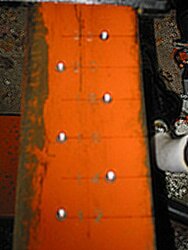
The othe related trick is something that my friend did on his splitter that can be handy... He marked the beam for measuring splits - by putting a few small drill "dimples" in the beam at critical intervals, you get a quick and crude measuring tool to see how long your splits are. It doesn't measurably weaken the beam, but can be real handy if you want to sort your splits by length...

Gooserider
 
yikes ... those fittings looks expensive!
 
_CY_ said:
yikes ... those fittings looks expensive!

Yup, try about $70 dollars worth... :gulp:

Gooserider
 
After a few months of looking at and seeing demo different splitters I ended up purchasing the same 30 ton unit as Gooserider about 3 weeks ago from the local HF retail store largely based on Gooseriders review. I was lucky also that my local store had just received one for another customer so I was able to physically see it before purchasing it. I have split about 2 cords of wood through the unit and am very pleased with its performance. I have so far no leaks and have not had to run this machine while splitting with the throttle open more than a third. It is very quit and splits with ease the various hard and soft woods that I split ranging from 6" to approx 2'in diameter. The build and quality of the unit is on par with the splitters at TSC and Home Depo, Sears and Lowes (Troy Built, Yardman, Cub Cadet). The deal clincher was I had a 15% off coupon which brought the unit price down to approx 1100 dollars. The only negatives I have found with the machine is the pin that holds the unit in the hor./vert position that's a bit of a chore to line up and ram control valve in the horz. position is a bit awkward but in the vertical position its fine. The ability to split in both the vert./horz. positions is great I split the smaller wood in the horz and the wood that's to heavy in the vert. The tow tongue has its plus and minuses its high position design is a little to high when towing the unit with my ATV and makes the unit tilt close to the ground. I towed the unit behind my pickup which has a higher hitch which makes the unit sit in a very nice level position and I towed it for about a 60 mile round trip and it towed very nicely. Storing the unit in the vert. position is nice it takes up very little room in my barn. Overall I am very pleased with the unit and my thanks to Gooserider and the other forum members who have taken the time to write about different splitters whether market or custom built.
 
be really careful towing any splitter with small wheels and small wheelbase.

they can flip over while towing, if you hit a large enough pot hole/bump... causing great damage, generally destroying splitter.

don't think it can't happen to you, as this has happened to several people towing small splitters.
mine tows great at highway speeds, but I know better.

keen427 said:
I towed the unit behind my pickup which has a higher hitch which makes the unit sit in a very nice level position and I towed it for about a 60 mile round trip and it towed very nicely.
 
I have had the 22ton version for a couple 3 years now and have had no problems with the exception of the coupling backing out. I reinstalled using locktite on the threads for the set scew. I did have the same problems with wood slipping off of the back plate like you said. I resolved that by drilliling and tapping the end plate then installing a bolt in that hole and cutting off the head of the bolt. I didn't use a very large bolt as it is only under compression. I haven't found anything it cannot split, mostly I split white oak and even the knotiest of wood will only slow it down to the point where it is shearing the wood. I made a 4 way slip on for the wedge which really works well. I was surprised that the 22ton would be able to drive that wedge as well as it does. I would really recommend you guys make 4way wedges if you have the chance as it really speeds up the proccess.
 
I agree, the little piece on the foot right now doesn't do a great job of holding angled or pointy rounds, so it does have a bit more of a tendency to kick out than I'd like. I'm thinking in terms of taking care of that next time I fire up my MIG welder - just haven't decided what sort of setup I'll add. (One thought is to make my initials or some sort of logo, which would have the effect of "branding" my splits - this could be a definite plus in the way of making evidence if anyone ever swipes your wood...)

Gooserider
 
Gooserider said:
I agree, the little piece on the foot right now doesn't do a great job of holding angled or pointy rounds, so it does have a bit more of a tendency to kick out than I'd like. I'm thinking in terms of taking care of that next time I fire up my MIG welder - just haven't decided what sort of setup I'll add. (One thought is to make my initials or some sort of logo, which would have the effect of "branding" my splits - this could be a definite plus in the way of making evidence if anyone ever swipes your wood...)

Gooserider

Wood stealing a big problem there in Taxachussetts?
 
Bigg_Redd said:
Gooserider said:
I agree, the little piece on the foot right now doesn't do a great job of holding angled or pointy rounds, so it does have a bit more of a tendency to kick out than I'd like. I'm thinking in terms of taking care of that next time I fire up my MIG welder - just haven't decided what sort of setup I'll add. (One thought is to make my initials or some sort of logo, which would have the effect of "branding" my splits - this could be a definite plus in the way of making evidence if anyone ever swipes your wood...)

Gooserider

Wood stealing a big problem there in Taxachussetts?

Hasn't been, but there are several threads on here if you look - seems to be a fair number of incedents every year, might be more this year depending on how much change Obama leaves us.... I probably wouldn't bother to mod a splitter just to brand my wood, but I figure that if you ARE doing it anyway, why not make it unique?

Gooserider
 
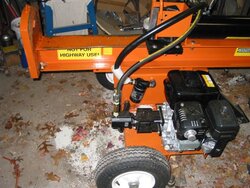
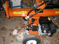
Pictures of todays splitter work - I am pretty much finished with this phase of the project. Eventually I want to turn the engine around so that it faces the other way (and blows the cooling air away from me), but that will be a project for another time, AFTER I get the current batch of wood finished.

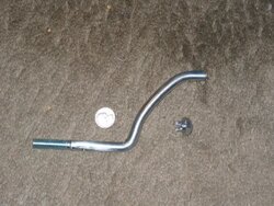
As I mentioned earlier, I was working on a replacement for that pin that locks the splitter into the horizontal or vertical position... I've gotten it almost done, except needing to weld or braze the stop washer and handle in place... It started out in life as a 10" long, 5/8" bolt - I should have used a 3/4" bolt as I had partial threads left after turning, but this will work... I turned one end down to make it the same diameter as the original pin, but gave it a bit of extra length (make it easier to get the clip in) I turned the head down on the other end, and cross drilled it for the clip and a 1/4" bolt that I had in my scrap bucket, and was just the right size to be a handle.


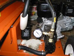
I also got the hydraulic filter relocated on the low pressure side, and added a high pressure "T" and a 3,000psi pressure guage on the high pressure line - this got me the needed slack in the lines after doing the earlier repositioning of the cylinder and valve.
 

Attachments

  • extended-pin-in-proc..jpg
    extended-pin-in-proc..jpg
    36.7 KB · Views: 792
  • side-view-pump-filter.jpg
    side-view-pump-filter.jpg
    72.1 KB · Views: 857
  • closeup-pump-filter.jpg
    closeup-pump-filter.jpg
    58.5 KB · Views: 796
Another shot of the guage...

I also added beam markings to give me a way to measure splits as I make them - 2" intervals from 12" to 22". The marking holes were made with a 1/2" drill, going just deep enough that the full diameter was starting to cut, and then I used a lettering set I got years ago (another HF special, purchased at 50% off) to mark the distances. This is crude, but IMHO a useful way of doing QA as you go along - reject the over-length splits before they make it into the wood pile.

Another project I finished today was my "up-stop" modification of the log ejector so that I get a shorter cycle. I put in three sets of holes, one inch apart vertically and staggered to keep everything strong.... Putting a 1/2" bolt through the holes should restrict the upwards travel enough to kick out the valve detent, giving me a short stroke. With the pin, I should have no trouble quickly changing from full stroke to short stroke mode.
 

Attachments

  • guage-1.jpg
    guage-1.jpg
    58 KB · Views: 819
  • mark-beam-2.jpg
    mark-beam-2.jpg
    38.8 KB · Views: 787
  • up-stop-holes.jpg
    up-stop-holes.jpg
    39.8 KB · Views: 794
  • log-ejector-upstop-in-use.jpg
    log-ejector-upstop-in-use.jpg
    51.6 KB · Views: 818
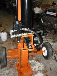
And a few other shots showing various parts of the fixes...
 

Attachments

  • vert-pos-show-fixes.jpg
    vert-pos-show-fixes.jpg
    64.6 KB · Views: 809
  • side-view-pump-filter.jpg
    side-view-pump-filter.jpg
    72.1 KB · Views: 754
  • upstop-and-valve.jpg
    upstop-and-valve.jpg
    44.6 KB · Views: 806
And....
 

Attachments

  • side-view-pump-filter.jpg
    side-view-pump-filter.jpg
    72.1 KB · Views: 749
Followup... Did some more splitting today with the improved splitter -

The new position on the valve is a BIG help, but the handle was still a bit high for a comfortable reach. The tab on the handle that actuall connects between the pivot and the valve spool is at a slight angle, with the lever pointing upwards as installed. It was a simple matter to pull out the two pivot pins and flip the lever over so that it angled down instead - this dropped the height of the handle knob by about 4" or so, and the result is just about perfect. (Sorry no pictures)

The split length markings aren't essential, but are a nice touch - I found them highly visible and easy to read while using the splitter. One thing I hadn't planned on, but it turned out they were very nice for was when making multiple splits from a single log, I could note the length and then very consistently return the wedge to the same height for a shorter cycle on the splits after the first.

The pressure guage is also kind of fun, though again not an essential. It's a 3,000PSI guage, per the recomendation of the guy at the hydraulic shop. I notice that the guage shows zero when the lever is in neutral, and 1-200PSI when the wedge is going up or down w/ no load. The upstroke detent kicks out around 6-700PSI, which also appears to be about the pressure where it starts kicking into high pressure mode. I didn't get any really gnarly chunks today, but it seemed most of what I was splitting was going at between 100 and 300PSI, IOW, not much more than it took to move the wedge! The only time I was able to get a higher pressure was when I was experimenting and holding the valve at the end of a stroke, at which point it would kick into low range and rapidly go past the end of the guage - I think I need to play with the relief setting!

OTOH, the up-stop limiter experiment was a TOTAL failure - The first time I tried it, the wedge didn't slow down, and I didn't even see a twitch on the pressure guage, the bolt was just totally ignored by the wedge - anybody want a nice 1/2" diameter steel pretzel?
 

Attachments

  • steel-pretzel-upstop.jpg
    steel-pretzel-upstop.jpg
    72.1 KB · Views: 717
Gooserider said:
Followup... Did some more splitting today with the improved splitter -

the up-stop limiter experiment was a TOTAL failure - The first time I tried it, the wedge didn't slow down, and I didn't even see a twitch on the pressure guage, the bolt was just totally ignored by the wedge - anybody want a nice 1/2" diameter steel pretzel?

Goose - that one gave me a good laugh - I'd read your plan to use the bolt as a limiter and assumed it would work fine - guess I was wrong too! Anyway, thanks for keeping up posted on your splitter modifications and improvements . I've done some (non-elective) work on my Speeco too, intend to post when I have time to put a report together with pics.
 
I think I need to play with the settings on the valve, as they seem to be set way to high for both the over-pressure relief and the upstroke detent kickout.

While I was splitting today I was watching the pressure guage fairly closely, and most wood split at between 300 and 500 pounds pressure, if it took that much, a lot of stuff I never even saw the guage move...

Lets see, I have a 5" cylinder, so my piston is 19.6 square inches.... Multiplying that out, If I have X pressure at the guage, I have Y tons at the wedge...

PSI Tons
100 0.98
200 1.96
300 2.94
400 3.92 = about what a small electric does
500 4.90
750 7.35 = about what a large electric does
1000 9.80
1250 12.25
1500 14.70
1750 17.15
2000 19.60 - slightly more than a 20 ton at 3,000PSI
2250 22.05
2500 24.50 - more than the max on a 4.5" cylinder
2750 26.95
3000 29.40 - My theoretical maximum at 3,000 PSI

I think the most I saw on the guage today while splitting was about 1500psi, in a very gnarly crotch that was fighting most of the way through it.

However the kickout pressure on the upstroke was well over 1,000psi and I think I saw it spike to over 2,000psi once... Certainly the engine seems to go into more "grunt mode" over tripping the detent than it does over all but the worst of gnarly logs.

Likewise, I haven't managed to stop the wedge mid travel yet, but if I hold the lever engaged at either end of the stroke, I rapidly go over 3,000psi - not sure how far over as it is only a 3,000psi guage and I stop before I over-range it...

I need to look up the manual on that valve for how the adjustments work and see if I can tone it down a bit.

I'm also getting a little bit of leakage with the new valve, but this time it appears to be coming from that hex cap next to the operating spool. It's also much less volume than the other valve, I might just need to tighten something up.

Gooserider
 
Bringing this thread back up to keep all my HF splitter notes in the same place. I got the following as a PM, and since it's stuff that could be of interest to others, I thought I should reply to it here, so as to avoid repeats of the same questions....

cityevader
Subject: HF splitter
Date: 2009-01-03 13:38
Recipients: <Gooserider>

Hello, I’ve got the same splitter, you may remember my “lengthy review” at arboristsite.com?

I think so, I know I read a bunch of reviews on both sites before getting my splitter.

I’m curious about a couple things. How did you rotate your cylinder only 90*? Is it that the ram rear pin no longer bearing the direct load, i.e. the end plate resting against the two vertical mounts? I was going to flip it 180 so I’d stand on the other side of the machine to avoid standing over the engine, but having the valve on top would be better. I actually want to flip the valve itself 180 so that the lever is even closer to the workpiece...of course, that’ll require flipping the lever as well, and some bracketry to hold the valve.

That was a bit of a tricky thing - the CYLINDER is rotated 180*, and attaches the same way it did originally, but I put a 90* elbow between the cylinder and the valve, so that the VALVE is only rotated 90*, and put on the opposite side of the cylinder... I imagine that if you wanted to keep the valve on the same side as original, you could put the 90* fitting in without rotating the cylinder. The trickiest part was actually doing the assembly, as the clearances are tight, you have to put the 90* fitting on the valve and tighten it to just the right position in order to get the valve to clear the cylinder when screwing the fitting into the cylinder.

It would be hard to flip the valve as the ports would interfere with each other, and it would also cause the lever to move opposite to the cylinder - I'd keep the valve orientation and possibly make a longer handle with some bends to put it where you want.

At any rate, I think it would be hard to get the valve into a position other than the way it came, or the way I have it now, without needing a LOT of additional fittings, and replacing the top (extend) high pressure line. I ended up getting a bunch of extra (expensive) high pressure fittings to make the stock hose work - in 20/20 hindsight, I would have come out a little better if I'd bought a new longer high pressure line instead.

Continued in next post...
 
Continued

Do you have issues of overly hot hydraulics? My ram temp gets to 180* after hardly 40 minutes. I called HF and finally got a tech who said the filter housing position is important, and to have the taper pointed out. I should have asked if he meant out in terms of flow direction or in terms of position on the tank, as I haven’t been able to get through again. I noticed your repositioned filter mount is backwards from mine. Was it originally in the same orientation did you notice? Can’t tell from your “before” pics.

I'm not sure how hot the hydraulics get, as I don't currently have a good way of measuring the temp. The old "touch test" (I can touch the metal parts for a few seconds w/o getting burned, but it's too hot to hold onto comfortably) suggests that they are only getting to a little over 100*, but who knows. I do wish they'd stay cooler.

I repositioned my filter housing as you noticed, but that was just to make the return hose reach. The filter housing is facing the same direction it came from the factory in terms of fluid flow. I seem to recall that the housing on my unit either had a flow arrow on it, or was marked "in" and "out", which is what I would have followed - remember the filter line is the return line that goes INTO the tank... If yours is backwards, I would expect it to cause problems and would need fixing - if you do though, be sure to change the filter as you will have been running fluid through it backwards, and reversing the flow would "backwash" all the crud out of the filter and back into the system.

Now according to a lot of the hydraulic info sites I've looked at, much of the heating one gets in a system is from the friction of pushing the fluid through the lines, which is made worse if the lines are undersized for the size of the pump. My interpretation of the recommendations suggests that the HF lines are undersized for the application, especially on the 16gpm pump units. However this doesn't seem to be unusual, as many of the splitters I've looked at appear to use similar size lines. I don't know if it would be worth upsizing any lines that were being replaced, or not (especially since it's supposed to be a sizeable price jump to to to the next size line) Even more so the question of upgrading an existing line that didn't need replacing.

The other factor that seems to be common to all splitters I've seen is that the fluid tank is FAR smaller than optimal - most of the "how to design a hydraulic system" sites I've seen suggest that the fluid tank should be at least as large as, and preferably twice the pump gpm rating. For a 16gpm pump, that would be 16-32 gallons. In actual practice most splitters seem to be closer to 5 gallons. My HF tank took about 4 gallons when I filled it initially, and took another gallon once I got the machine running and filled the cylinder and all the plumbing.... I don't know if it would be worth trying to put a transmission cooler or similar in the return line, or possibly try attaching some sort of cooling fins to the sides of the fluid tank to increase the heat dissipation.

I’ve run about 14 cords through it so far, and want to start heavily modifying it, but am considering returning it, and would be problematic if permanantly modified.

Well thus far, all my mods except the effort at making the short stroke kickout on the valve, and the log length marks have been completely reversible (Indeed I'd want to reverse them just to get my fittings back!) The next phase of mods will probably be harder to undo w/o leaving a trace - I want to spin the engine 180* to make it blow the cooling air away from me, and make it easier to reach the controls among other things.

Gooserider
 
Ahh, I looked over your pics again. My mind stopped at the one where the ram's inlet port is straight up and a screwdriver was holding it in and I thought that was where it stayed. Now I see in the other pics it is indeed rotated 180. Thanks for clarifying.

Being winter now, the hot air blowing is a good thing, but last summer it was unbearable. Need to do a bit of welding to extend the "deck" which the engine sits on to rotate it 180*

With other projects in the works, I have a feeling it'll be awhile until I can start the valve relocation project.
 
cityevader said:
Ahh, I looked over your pics again. My mind stopped at the one where the ram's inlet port is straight up and a screwdriver was holding it in and I thought that was where it stayed. Now I see in the other pics it is indeed rotated 180. Thanks for clarifying.

Being winter now, the hot air blowing is a good thing, but last summer it was unbearable. Need to do a bit of welding to extend the "deck" which the engine sits on to rotate it 180*

With other projects in the works, I have a feeling it'll be awhile until I can start the valve relocation project.

Yeah, the screwdriver part was a temporary thing to hold the cylinder with the ports facing up in order to make it easier to work on from either side... It worked well as a technique though, the cylinder never budged while I was doing the work, and considering the amount of torque I was using on some of the fittings, that was impressive (per my pipe dope bottle, I was supposed to do 3 turns past finger tight, and the last turn was often a real battle...)

I found the problem with the hot air blowing at me was that it had a tendency to pick up any dirt, sawdust, or whatever on the logs and blow it in my face... I didn't mind the temperature as much as I did the dirt, which always seemed to find it's way around my glasses.

However I don't know about needing to extend the deck for the engine - On mine the engine is sitting on the deck extension, and spinning it around would presumably put it on the platform next to the oil tank. I don't have exact measurements, but it looks to me like if you drilled new mounting holes for the engine on the platform, so that the engine base was flush with the rear end of the platform, then it should fit nicely w/ no welding needed.

The only question I have is whether there is enough room between the tank and the tire to fit the engine in between, and whether there would be any interference from either the filter or the suction line outlet. Obviously there would be a need to replace all three hoses, and I'd need to modify the suction inlet on the pump to change it from a right angle inlet to a straight one, or perhaps change the way the pump is mounted.

Other items on the "to do list" would include trying to get rid of some of the slop in the beam mounts, and possibly reinforcing the tank a bit (I've heard reports of leaks from people that tow the units a lot) I'd also like to improve the horizontal lock to make it easier to get the pin into place, and make it possible to point the brace leg straight up in order to get it out of the way when storing the unit with the beam vertical (minimizing the needed footprint area)

In the totally wild fantasy realm would be to add a hydraulic motor that would let me "drive" the unit around the yard without needing the lawn tractor or other towing vehicle...

Gooserider

Gooserider
 
I did initial measurements on the engine mounting, and there was a good 3 inches of interference if flipped around...I can't remember exactly which direction, but the mounts would have to come away from the tank and towards to hitch ench by about 2 inches each I believe. It might be easier to fab up a large metal shield to block the wind/dust, as well as angled to cover the pump/gauge to protect from falling splits.

Wild fantasy?....have some sort of channel mounting for the toeplate to slide into to make it removeable, so a wedge could be slid in, quickly changing from sliding wedge to fixed wedge....also a bigger/quieter muffler....maybe a remote/auto throttle that would kick down when return stroke completed.
 
Status
Not open for further replies.