Breckwell controller switch needed - any thoughts.

  • Active since 1995, Hearth.com is THE place on the internet for free information and advice about wood stoves, pellet stoves and other energy saving equipment.

    We strive to provide opinions, articles, discussions and history related to Hearth Products and in a more general sense, energy issues.

    We promote the EFFICIENT, RESPONSIBLE, CLEAN and SAFE use of all fuels, whether renewable or fossil.
Status
Not open for further replies.

nanoman

New Member
Nov 24, 2008
12
North East
Hi,

I have an breckwell controller and I am looking for a replacement rocker switch SPDT (mom)-off-on (it controls manual feed and high fan)

I have attached an annotated photo of a breckwell controller (the switch needed is the one on the left).

I have not been able to find a replacement ROCKER switch (I have looked at Jameco, Mouser, DigiKey, etc.).

I believe the original switch is C&K;7107J3CBI2 spdt mom-off-on
equivalents may be : NKK M2019TYA03-JA or E-Switch 300SP-5J3M2RE

I am a novice and I am not familiar with the circuit. Annotations are just a guess. I take no responsibility for any of the information.

Does anyone know where I can purchase 1 or 2 of these switches or an equivalent "rocker"? There are a lot of the SPDT (mom)-off-on toggle switches but I don't find the "rocker" versions. It would be nice to have a replacement rocker insteads of the just functional equilavent toggle.

Thanks.
N. Man
 

Attachments

  • controller.png
    controller.png
    70.9 KB · Views: 4,819
  • wiring.jpg
    wiring.jpg
    85.6 KB · Views: 7,430
If you aren't concerned with the looks of the new switch, you can use any similarly rated switch that functions the way the original did. The problem will be that most likely and switch except the original won't allow you to use the glamour cover (plastic rocker cover). You might end up with the toggle sticking out at you. If you look up the part number of the original switch you should be able to get the ratings (volt, current) for the switch and match it to another if the original can't be located. The current should be pretty low but make sure to replace with at least the same ratings.

The sources you mentioned for locating a new switch have so many switches that searching through them can take forever. That's why I mentioned that if you can live with something that looks different but functions the same you'll have an easier time. Make sure to note the connections to the pcb to make sure you get a pcb mount switch since you'll have to rework the pcb a little to remove (unsolder) the old and solder in the new switch.

Just out of curiosity, why do you need to replace the switch? What happened?

Good luck
 
Ok, so here is the story (I am just a novice in this endeavor).

1. Symptom: the auger would not auto feed (at this point, I was unaware that the thermodisc was damaged, the short had occurred and that it "blew" the fuse and damaged the Q2006QR power Triac.)

2. I tried the manual feed (which is the SPDT C&K;switch) and poof! (well more of a pop).

3. What happened / Cause: the auger thermodisc (60T22) failed. In fact, it broke off and "shorted" the auger power leads (yellow and orange) to ground.
Primary failure was the thermodisc mounting. Secondary failure was short blew fuse and damaged Triac. Third failure of the switch was do to me not properly investigating the why the auger would not auto feed (this symptom is typically due to failed open thermodisc) prior to trying manual feed.


Situation: Bad Thermodisc, blown spdt Switch, blown fuse and damaged triac (should have been protected by fuse but it's a slow fuse). And most importantly NO HEAT !!!

Options:
analog controller no longer available from Breckwell. So retrofit with new digital controller, send out analog board for possible repair or try to fix myself.


I reviewed the board and chose to fix it myself (or at least give it a shot). The annotated controller board photo is my notes on the board from looking at it and using a simple VOM meter (and may not be correct).

1. Q2006R4 Triac was not readily available but funtionally equivalent replacements (for this application): Q4006R4, Q4006L4 and Q2006L4 are readily available from Mouser electronics. so the Q4006R4 is most robust than the Q2006R4 and has same "firing characteristics")
R = non-isolated tab
L = isolated tab
2 / 4 = 200 or 400 PIV
6 = 6 amp rating

datasheet ref: http://www.littelfuse.com/data/en/Data_Sheets/E2Triac.pdf


2. Fuse readily available (anywhere).
3. Identical switch not available, however, toggle versions of the 7107 switch are readily available.


By the way the 7107 series (mom-off-on rated for 5A @ 125 VAC) datasheet is readily available on the web at many sites.
The 7107 series comes in many configurations and you need the (on)-off-on version!
Mouser, digikey and others have cool switch filters to quickly narrow down your options for funtionally equivalent switches (it's a lot simplier than manually searching through a catalog). And always remember there are numerous surplus places on the web that my have exactly what you are questing for.

datasheet ref: http://www.alliedelec.com/Images/Pr...CANDKITTCANNON_INDUSTRIAL-CONTROL_6763000.PDF


This SPDT switch is momentary manual auger feed (auger motor is 125 VAC @ 1.65 A, 4 RPM | "starting current pulse higher") and on for the high fan.


Pellet stove is currently operating without the SPDT switch. But you don't have manual feed control.


Solution: Someone was kind enough to offer me a replacement switch. Hopefully it will arrive in a few days.

If this doesn't work out, I will order a NKK switch from Mouser (probably a M201901D)

Alternate "functional equivalent" switch datasheet http://www.nkkswitches.com/pdf/MrockersFlatFrame.pdf


Lessons learned: know more about a pellet stove and hopefully better problem solving skills (that stick).
N. Man
 
Sounds like you have things under control. Since the auto feed is functional then your replacement choices sound reasonble. The fuse WILL NOT protect a triac under those conditions even if you have a fast blow fuse because the instantaneous current is simply too high too fast. At least the opto was in the design to protect the rest of the circuitry so the fix is relatively simple. I am surprised that the switch was damaged though, they tend to survive short events relatively well, especially when fused.

If you have any more issues while performing the repairs, feel free to contact me as I have a fair amount of experience with power circuits as well as pcb rework.


Pelletcanadian,

We need more info in order to offer assistance. Is it the same stove(brand) with the same electronics? Does this occur in manual or are you running a thermostat? Any other info you can provide can help us in helping you.

Rgds,

Dan
 
Dan,

Yes, I agree that the instantaneous energy transfer for a shorted condition will "blow" by the fuse and adversely impact the 6 Amp Triac).

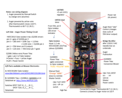
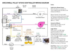
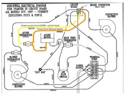
I will probably add a M.O.V. (metal oxide varistor) for general surge protection and 3 in-line fuses between (A) the Molex connector and the auger motor [orange wire] (vs just the auto auger feed yellow wire), (B) Molex connector and the thermodisc for convection blower [blue wire], and (C) the Molex plug and the combustion blower [pink wire] . In-line fuses are cheap and will better protect the controller board from several failures leading to electrical shorts.

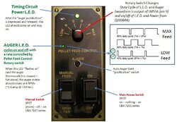
Strangely (at least in my opinion) the Manual Feed Switch is not fuse protected so it basically cooked. Personally I thought the PC board trace would burn before the switch. Maybe the switch failure is just coincidental or it was on the edge of failure and this event pushed it over.

In any event, I am back in operating condition. That is, the pellet stove is cooking (better stated, it's heating). :)

For the Over Feeding Response:

I am a novice at best and by no means competent in Pellet Stove controllers. With that said.

For the controller I worked on, here was my approach (this may not be appropriate for your controller):

My controller is an old Analog Controller. And I don't have a thermostat connected.

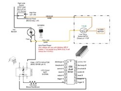
The yellow wire is for automatic periodic feed and is powered by the Q2006R4 triac.

The Q2006R4 triac is basically a switch that connects 110VAC to the auger (if the thermodisc is closed [stove hot]).
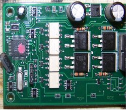
This Q2006R4 triac (switch) is controlled by the MOC 3010M opto-isolator.


WARNING: If improperly done this could result in board damage and / or electrocution.


For my work, I disconnected the controller board and temporarily wired it to a 110 VAC plug. This way, I could work on it on my workbench. With the power off and unplugged, I carefully connected a VOM (volt-ohm meter) lead to the "white power lead" and the other lead to the Yellow wire (and selected VOM to measure 110 VAC). Put the controller on a piece of wood or other insulating material.

In addition, connect the Auger motor to Yellow Lead and to White Lead. NOTE: If there is no load (if the motor is not connected), the Triac's output (yellow wire) will alway indicate 110 VAC and you will not be able to evaluate the Triac's switching function. With the motor connected it should cycle on and off when the Auger LED cycles on and off.

If the AUGER LED is cycling on too frequently it's probably due to the Resistor & Capacitor components (or possibly the diode required for a less than 50% duty cycle) connected to the LM556 timer. There are many tutorials on 555 /556 timers. The LM556 timer is just two 555 timers in the same 14 pin package. I believe the adjustable resistor pot allows for adjustment of the auger cycle period time. If all is working, then adjusting this pot may be the correct and easy solution. I will confirm when I install the new switch next week.

Ref: http://www.kpsec.freeuk.com/555timer.htm (better, covers 555 and LM556)

Ref: http://www.uoguelph.ca/~antoon/gadgets/555/555.html


Plug in via a power strip and use the power switch on/off to power control board.

1. Power On
observation: Neither LED should be on.


2. Depress auger pushbutton.
observation: Timing Circuit Power LED at TOP Center should come on and stay on.
after a 1 minute of so, the Auger LED should cycle on and off. The time on and off is controlled by the
pellet feed control (which changes the RC components connected to the 556 timer).


3. Does the auger motor come on only when the Auger LED is on? So the Auger motor should rotate only when the Auger LED is on.

4. Does changing the Feed Rate Switch change how long the Auger LED is on?

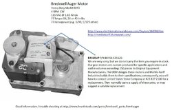
5. Do you have the original Auger motor installed. Is it possible that you have the 4 RPM motor instead of the 1 RPM motor. My unit uses the 4 RPM heavy duty motor. My understanding is some Breckwell Pellet Stoves use the 1 RPM motor.

Just my thoughts. I am sure others will chime in. I am glad for this forum, it provides some great information thanks to some helpful folks.

Good Luck.

N. Man
 

Attachments

  • faceplate4.jpg
    faceplate4.jpg
    100.1 KB · Views: 3,036
  • AutoFeed.jpg
    AutoFeed.jpg
    65.1 KB · Views: 2,671
I have a Breckewell P28I with an analog board. I thought maybe it was bad (long story) but it wasn't board and stove works fine. Anyway before I found this forum I left a message on some company's site. Had a message on my answering machine next day saying they contacted Breckwell tech dept and the had a few boards left. Offered to get one for around $300. Did some checking and found board wasn't the problem so didn't pursue. Maybe you shoud try calling Breckwell directly and asking if they have one.

Breckwell Hearth Products
2915 E. Randol Mill Road
Arlington, TX 76011

Phone: 866-606-8444
817-652-9602
FAX: 817-652-9635
 
KBD627

I believe my issues were resolved by the repair work I described above (replacing thermodisc, fuse, Q2006 Triac, Switch).

Thanks for the suggestion of calling Breckwell. It's a good idea to check with the manufacturer (plus they have the stove manuals with wiring diagrams on their website). I had already contacted Breckwell and their response was as quoted below. The expense of buying the digital controller (and associated wiring harness) and the controller's limited circuitry encouraged me to attempt fixing the board. I am glad I did.

Ref website: http://www.breckwell.com/manuals.asp

Ref website (controller boards) http://www.hearthtools.com/parts/Breckwell_Contro_ Board_chart.htm


Breckwell E-mail response:

It sounds like you have really focused on the control panel well, and it may indeed be the cause.

The best way to trouble-shoot this unit is to simply bypass the three thermodisc and the air switch. If the unit still does not function correctly then the problem is indeed the control panel. That particular control panel is no longer available, but you can upgrade to the digital by calling customer service at (866) 606-8444 ext 112 and asking for the 950 upgrade kit.

If bypassing all three thermodisc and air switch does cause the unit to function correctly, then you most likely just need a new thermodisc. Reconnect each thermodisc one by one and when the unit no longer functions correctly you have identified the problem.

Sincerely,

William P. Wilson
Technical Support Manager
Breckwell Hearth Products


N. Man

P.S. I included the 4 RPM Auger motor graphic just because it came up in my information searching.
 

Attachments

  • 4 RPM Motor.jpg
    4 RPM Motor.jpg
    91 KB · Views: 2,506
nanoman

Wow, I wish it was that easy to fix the digital boards. I have a problem with the #1 setting. Doesn't turn the auger motor. all other settings feed the pellets.

I don't use #1 much, But thats the setting that is default from a power reset. Sometimes I come home to a very cold house!

Wish there was a diagram some where!

I also wish we could change the speeds times on the lower settings.. 1+3, 1 and 1+4 are pretty much useless for my bigE stove also wish 2 was a little hotter as well. But from 3 on the stove cranks out some good heat.

But I have to say I learned much from this.

Thanks for the good read and nice links.

jay
 
Off the top of head, probably you could effectively can the speeds by using a different auger motor. For example, exchanging a 1 RPM motor with a 4 RPM motor. This should make all the speed settings 4 x faster. Not elegant but should work.

Which digital controller do you have? Possibly I have some information on it (residual from my noodling around on the analog controller).

N. Man
 
I have the C-E-401 board. with the C-E-402 sticker on the relay.

I tried a 4 rpm motor on 1 setting long ago and dump as many pellets as the 5 setting with 1 rpm motor. My local dealer gave me the 4 rpm by mistake. stove just over-heated.

Not a safe way to go. I might try a 1.3 rpm from a quadrafire 800 or a 2 rpm from a englander. Still would over fire the higher settings though! So would have to play with the timers to tweak them also.

But all I want for now is to fix the no feed on #1 setting.

I would like any info or links you can send please?

jay
 
Yes. You have to choose the motor carefully.

There may be a simple adjustment on the board. Have you asked the vendor.

I assume that your board uses a power triac (2006 or similar) and an opto-isolator connect to the MPU (digital controller).

If this is true, placing a JK flip flop between the LED input of opto-isolator and output of MPU will 1/2 the speed. A 555 Timer could be used to make an adjustable pulse width fraction of the digital controller signal.

So what happens: the triac will turn on once (1) for each two (2) pulses. A 1 RPM system with a 4 RPM motor and J-K flip flop mod will operate as a 2 RPM motor. (or simply get the 2 RPM or different speed motor). The 555 timer add would permit a 4 RPM motor to effectivity operate from 4 RPMs to 1 RPM (resistor pot adjusted)

Just some NOT WELL THOUGHT OUT ideas.


I will check my notes for your controller tonight. Can you forward a photo of it?

N. Man.
 
nanoman

Not the same beast with the digital board.

It has no resistor pot to adjust. There are 4 seperate timer controls for 2 thru 5 settings. They are made up of an MOC 3031 or 3020 optoisolators and T835 600G triaccs. I think it has a pic to control them.

I don't see any resistors to play with. would'nt be that easy I guess!

As for the 1+3, 1 and 1+4 settings I think that has something to do with the H11AA1 optoisolators.

I can't take a photo right now the stove is running. I will try to shut it off later.

How do you want me to send the photo to you?

jay
 
Cool. Yes I would like to get a photo.

Albeit digital or analog the controller should feed varible duty cycle (on / off) pulse to the auger motor. To protect / isolate the PIC from the Triac (motor switch) the Opto-isolator is used.

Analog system uses R x C with switched selected "Resistors" for the timing (on / off duty cycle of auger). I assume the Digital system uses either seperate I/O inputs for the timing (on / off duty cycle) or one debounced input to cycle through the various speeds.

N. Man.
 

Attachments

  • breckwell digital.jpg
    breckwell digital.jpg
    9 KB · Views: 2,078
nano

I found an Ace number on the board 169894

I also sent pm for email. I took some photo's(large ones)

jay
 

Attachments

  • 01.jpg
    01.jpg
    188.1 KB · Views: 2,191
nanoman,

After some head beating, I think the times are set by the Atmel AT89S52 microcontroller. Thats something I don't want to play with. And I don't have the tools needed anyway!

So, If I wanted to change the speed of my auger motor to 2 rpm's. Could I make an interface that is in circuit and adjustable?

Full at low speeds and adjust to control the speed in the high 3-5 speeds. Something that has a pot like the older boards.

It would have to not increase the total amp draw on the board for sure and Be able to handle the timed pulse's.

Any thoughts??

jay
 
Hello, looking for some help after seeing the cost of replacement controller boards...

P-321 controller will operate fine for 5 to 25 minutes then the auto-feed will stop turning the auger, however the auger led still lights in perfect timing and the manual feed works as well. i was suspecting the relay but i an open to expert/experienced opinion.

also, igniter failed to glow twice but not always associated with first issue.
 
Thanks for the wealth of information on the Breckwell. I was wondering if you had any insight as to why the auger would run all the time once the stove is plugged in. If I disconnect the yellow wire on the thermodisc it will stop turning and the manual feed will still work. I have checked the yellow wire from the control board and it shows the same voltage whether the green led on the control board is on or off. I tested the manual feed and it shows no voltage until the switch is pressed and then it shows the same voltage as the yellow wire has all the time. Thinking maybe the same Q2006R4 resistor that was talked about in earlier posts but not sure.

Thanks
 
wbcease said:
Thanks for the wealth of information on the Breckwell. I was wondering if you had any insight as to why the auger would run all the time once the stove is plugged in. If I disconnect the yellow wire on the thermodisc it will stop turning and the manual feed will still work. I have checked the yellow wire from the control board and it shows the same voltage whether the green led on the control board is on or off. I tested the manual feed and it shows no voltage until the switch is pressed and then it shows the same voltage as the yellow wire has all the time. Thinking maybe the same Q2006R4 resistor that was talked about in earlier posts but not sure.

Thanks

wbcease,

Check the thermo disc. It sould be Normally open with no heat.

jay
 
Thanks for the response. I did some further testing on it and found that this P32 stove seems to have a lot of extra wiring that does not show on any schematic. Figuring someone wired a thermostat at one time. Anyway, I cleaned up the wiring to what is in the schematic and tried it. Now the stove will start and the auger will not turn until the temp reaches the low temp thermodisc minimum. At that point the light cycles on the board, but the auger runs constantly. I tried the connection across the thermodisc and of course that makes no difference. From what I can see the thermodisc is staying closed and not letting the power to the auger until the temp is right but it seems that the circuit board is sending a constant voltage to the auger all the time even though the LED is cycling. Wondering what on the board controls the cycle of power to the auger.

Thanks....
 
Well if the Q2006R4 triac failed it might do that, But they normally fail open, Meaning it would not feed at all.

Might be better to wait for nanoman, He is more familiar with these boards.. I only have a newer digital board.

jay
 
Status
Not open for further replies.