Progress on Splitter rebuild

  • Active since 1995, Hearth.com is THE place on the internet for free information and advice about wood stoves, pellet stoves and other energy saving equipment.

    We strive to provide opinions, articles, discussions and history related to Hearth Products and in a more general sense, energy issues.

    We promote the EFFICIENT, RESPONSIBLE, CLEAN and SAFE use of all fuels, whether renewable or fossil.
Status
Not open for further replies.

michaelthomas

New Member
Feb 10, 2006
286
I was contemplating selling the old girl and had a change of heart. I like the set-up and I know what I have. So far I have taken her apart (the easy part), power washed and scrubbed 20 years of baked on hydrauilic fluid and grime off, primed, painted and have begun re-assembly. I bought a new Prince detent valve, and a 16gpm Haldex pump. The direct drive should decrease a-lot of the vibration and am hoping for faster cycle times. I still need to get new hoses. I am a bit stumped on how to attach my filter sytem to the new pump. The filter bracket has 1 1/4" pipe thread that was attached to a barbed flange and a 1 1/4" hosethat fed the intake on the old pump. I am having a hard time finding 1 1/4" hydraulic fitting to reduce down to a 1" hose for the 1" intake on the new pump. any recomendations? In the pictures below the filter is on the left side (the filter is removed as I have been taking it to check fittings). Any thoughts on how to configure the hoses for ease of use and longevity? I think I am going to have to take the suction line up and over cylinder to get to the pump. There is a 2" hole drilled in the beam right around where the hose would come off the filter? Thank You
 

Attachments

  • 100_0141.jpg
    100_0141.jpg
    44.7 KB · Views: 519
  • 100_0142.jpg
    100_0142.jpg
    42.8 KB · Views: 539
  • 100_0143.jpg
    100_0143.jpg
    46.1 KB · Views: 514
  • Splitter.jpg
    Splitter.jpg
    76.8 KB · Views: 522
DO NOT put the filter on the intake line to the pump!!! (Unless you really like purchasing new pumps...)

The ONLY thing that should be between the tank and the pump is possibly a fairly coarse filter screen, and many hydraulic people would even object to that. You want as straight and short a path from the tank to the pump input as you can manage, with minimal restrictions - NO fitting should be smaller than the pump inlet. Ideally the pump should be lower than the tank fluid level, but this isn't always possible, however you should at least attempt to minimize the suction head.

The reason is you want to make sure the pump suction side doesn't cavitate, and in effect make the pump run dry - this will rapidly ruin the pump. To avoid it, you want to make sure that there is no restriction in the suction line.

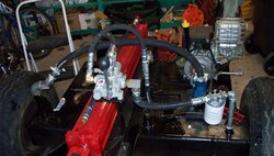
The filter should be in the low pressure RETURN line that goes from the valve back to the tank. Make sure you plumb it so the flow goes in the proper direction (it should have a flow arrow on the housing). It is probably best to put the filter so that it goes directly into the tank, preferably below the full line (reduces air bubbles in the fluid) and then attach the return hose to the filter as this minimizes the number of fittings needed.

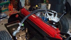
Otherwise, your hoses need to be long enough to go from point to point without straining or excessively tight bends. If the splitter tilts, make sure the hoses work in both positions, and going from one to the other. Avoid twists in the hoses. Try to keep them as short as you can while meeting the other guides - make them as long as they need to be, but no longer...

Remember, the high pressure side - pump to valve, valve to cylinder (both sides) need to use high pressure rated hoses and fittings (3,000 PSI minimum working pressure, NO Schedule 40 plumbing fittings, no hose clamps, etc.) The low pressure side - valve to tank, tank to pump, can use any suitable oil resistant hose, and it is OK to use plumbing fittings, hose clamps and so on.

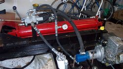
The valve needs to be solidly mounted - not just screwed into ONE of the cylinder ports - it is OK to have it screwed into one port and run a RIGID metal line to the other port, as this gives two solid points so that it can't turn. If not, you should make some sort of hold down bracket. Otherwise the constant cycling of the valve will cause it to loosen up and leak.

Hope this helps...

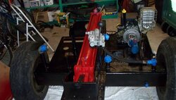
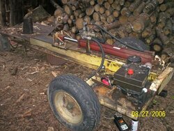
Good job on the rebuild job so far, looks good. (BTW, you mentioned a new pump and valve, looks like a new engine as well???)

Gooserider
 
I agree with your rebuilding plans...better off with the devil you know.
 
Gooserider said:
It is probably best to put the filter so that it goes directly into the tank, preferably below the full line (reduces air bubbles in the fluid)...
If the filter body is below the fill line, the oil will spill out when you unscrew the filter to change it. You can mount the filter body above the fill line and still have the return line below it.

That reminds me, I need to change the filter on mine.
 
Wow that looks awesome! Bet it looks better now than when it was built! Can I borrow it now? :)

Ray
 
LLigetfa said:
Gooserider said:
It is probably best to put the filter so that it goes directly into the tank, preferably below the full line (reduces air bubbles in the fluid)...
If the filter body is below the fill line, the oil will spill out when you unscrew the filter to change it. You can mount the filter body above the fill line and still have the return line below it.

That reminds me, I need to change the filter on mine.

True, if the filter itself is below the fluid level you might loose some fluid when changing the filter - I don't see this as a huge problem.

The point that I was trying to make though, is that it is better if the fluid goes back into the tank below the fluid level, as opposed to just spraying in the top. This will reduce the amount of foaming that can occur, and keeps the fluid from picking up a lot of air bubbles...

However most of us don't have a lot of choice in our tanks, since we have to deal with whatever the manufacturer gave us, so it's a case of doing the best you can with what you've got.

Gooserider
 
I have a few questions as I progress...
When assembling the plumbing on a splitter project should the hoses be partially filled with fluid as the connections are made?
I would imagine you would fill the filter with fluid prior to installing?
Pour fluid into the intake hose and into pump prior to final clamping?
How much elevation will a 16gpm pump with a 1" inlet be able to overcome without cavitation. My pump is above the tank and suction pipe is on the other side of the deck from the pump. The intake hose will have to be routed over the cylinder to the pump. the pipe is 6" into the tank and extends about 10"out of the tank, then another 12" or so to clear the cylinder and then a down hill of about 12" into the pump inlet. Each time I start this will the inlet hose be partially empty because of gravity?
 
michaelthomas said:
I have a few questions as I progress...
When assembling the plumbing on a splitter project should the hoses be partially filled with fluid as the connections are made?
No need, and would make things really messy!
I would imagine you would fill the filter with fluid prior to installing?
It won't hurt, but if the filter is on the return line, again no real need (It will fill itself as soon as the unit fires up, and it doesn't do anything critical that needs lubing while it fills.
Pour fluid into the intake hose and into pump prior to final clamping?
Normally I would say not, but in your case with the big pump suction head, it wouldn't hurt...
How much elevation will a 16gpm pump with a 1" inlet be able to overcome without cavitation. My pump is above the tank and suction pipe is on the other side of the deck from the pump. The intake hose will have to be routed over the cylinder to the pump. the pipe is 6" into the tank and extends about 10"out of the tank, then another 12" or so to clear the cylinder and then a down hill of about 12" into the pump inlet. Each time I start this will the inlet hose be partially empty because of gravity?
That sounds like a really long and ugly run... is there any way you can avoid the up and down steps - possibly drill a hole in the web of the beam for the hose to go straight through? If you can't do anything to straighten out the run, at least make the bends very long and sweeping rather than sharp corners - remember that every bend adds considerably to the flow resistance - effectively several times the nominal length of the run.

What I have seen suggested to "prime" a splitter setup is to tie the control handle into the down position, and then pull the engine over by hand (ignition off, and you may want to pull the plug just to make it easier to pull) until the piston starts to move. Then start the engine (run it slow if you have an adjustable throttle) and cycle the piston up and down 10-12 times, with no load. Expect that the motion may be very jerky at first as the air gets purged from the plumbing (keep all body parts clear!), but it will smooth out - obviously keep an eye out for leaks, and stop if you see any. After that stop and check your fluid level - it will probably be down at least a gallon as this is what gets used to fill the pump, cylinder and all the hoses.

Once you have the system full, and purged the air, you should NOT have any significant drainage of fluid from the rest of the system into the tank - essentially there is no way for air to get back into the lines to allow them to drain without pulling a vacuum.

Note that when connecting the lines, some hydraulic fittings are compression type that should NOT have any kind of thread sealant applied to them, while others are NPT pipe thread, which should be sealed, I like to use pipe dope - my brand of choice is Rector-Seal, but which one isn't a big deal. Teflon tape can also be used, but be careful not to block any pipe ends with it, and to not allow fragments to get into the system, as they can cause problems for all the parts...

Gooserider
 
That sounds like a really long and ugly run... is there any way you can avoid the up and down steps - possibly drill a hole in the web of the beam for the hose to go straight through? If you can't do anything to straighten out the run, at least make the bends very long and sweeping rather than sharp corners - remember that every bend adds considerably to the flow resistance - effectively several times the nominal length of the run.


Gooserider[/quote]

I do have a hole in the webbing but it would require a significant bend sharply to get the hose from 1" below the pump to up on top of the pump in a 12" area. I think from what you are saying about sharp bends that I might be better off going up and over. I think it will be a 38" run or so. I am hoping to have this up and running today. I need a new filter set-up as my old one was the 35 gpm with 1 1/4" fittings and I had to use the port that was connected to the larger intake on this pump. I assumed that reducing down the fittings to run a 1 1/4" down to a 3/4" fitting and 3/4" hose would cause too much resistance. Is that correct?
 
On my splitter the inlet is on the bottom side of the pump, with the outlet on the top, so I'm not quite sure I follow you. (and have been having trouble figuring it out from your pictures) Note that your pump's bolt pattern is symetrical, so you can rotate it if that will make the fittings line up better.

If those big pipes sticking up out of the tank are your suction and return fittings, then I would suggest shortenning the suction side, putting the pump with it's inlet either on the bottom or sideways, and running the suction line from the tank to the pump either under the beam or through the web - get rid of a lot of the extra plumbing with associated suction head issues.

On the filter, I assume you are putting it in the return line? If so, you want to have the filter be the same as the return line outlet on the valve.

Your plumbing should be something like this...

1. Tank to pump inlet - suction line, should be as short and straight as possible, MUST be a non-collapsible hose, must be as big as the pump inlet.
2. Pump outlet to valve - HIGH PRESSURE line - 1/2" minimum diameter, theoretically ideal is same as smaller of valve inlet or pump outlet, (usually 3/4") but that gets expensive, 1/2" will do the job.
3. Valve to cylinder (both ends) - HIGH PRESSURE lines, should be same as valve ports or cylinder connections, which ever is smaller, or 1/2".
4. Valve to tank, via filter - low pressure line, should be the same size as the valve outlet (probably 3/4") larger is OK, filter unit must have at least as high a flow capacity as the pump output, more is better.
 
I have it all plumbed. I got all new hoses and fittings. Went to a place called Gorham Hose and assembly with my pictures and they were great! Put together everything like a puzzle for me and everything fit. I filled the suction hose with fluid and turned over the engine to prime the system while my 5 year old helper held the detent open. The piston started to move, I reconnected the suction and started the engine on low. Cylinder goes in and out, turned up a bit and in and out, a bit more and in and out and then it started overflowing fluid through the fill and vent cap. I added more fluid to it and think I just added too much? How much air space should be in the tank? The pressure gauge is in between the Pump Outlet and the detent valve. What pressure shold I be seeing on it when it is running? It doesn't seem to be reading any pressure? I haven't put a log into it or put it under and pressure yet. I was unable to use any of the other stubs for suction as they don't go down into the tank and none of them were 1" which is what my pump intake calls for. Does the overflow sound like it was an overfill problem or air in the system problem. How do I tell if everything is working as it should? One small leak at the gauge union. I will re dope and tighten. Attached are pictures!
 

Attachments

  • 100_0156.jpg
    100_0156.jpg
    48.5 KB · Views: 331
  • 100_0157.jpg
    100_0157.jpg
    53 KB · Views: 308
  • 100_0158.jpg
    100_0158.jpg
    47.8 KB · Views: 322
The valve would be open centre so no pressure is expected to show with no load. When you bottom out the cylinder retract, you should see a pressure spike. A fully retracted cylinder holds less oil than a fully extended one so it's possible to overflow the reservoir. The oil will also expand with heat so expect more to overflow.
 
You should not show any appreciable pressure when the valve is in neutral. Maybe just enough to move the guage off the pin, but that's about it. Extending and retracting the piston w/o a log or other resistance, will show a little more, but not much - on my machine I show about 300 pounds when the system is stone cold, or about 150 when it warms up. If you keep holding the valve open when the piston hits full travel (in or out) the pressure should build till the relief valve opens, and you will probably also bog the engine a little.

When splitting, the pressure will vary depending on how tough the log is - an easy round will barely show any increase over what you have just moving the piston. A really gnarly chunk will show more. Essentially when you get into a tough chunk the wedge will slow down, and pressure will build until either the log lets go, or you pop off the pressure release, usually the log goes first...

As to the fluid level, unless you have a dipstick or other item that says otherwise, you want to have the fluid level an inch or two below the top of the tank when the system is at operating temperature. Hydraulic fluid does expand a significant amount when heated, so measuring it while hot is the best approach.

Keep the fluid level on the low side until you have everything sorted - remember that the plumbing holds a gallon or so, and if you have to drain it to fix something, that will raise the tank level. Once it's working you can top up as the plumbing should NOT drain when the machine is not in use.

Gooserider
 
I got her up and running tonight and the overflow problem had gone away. I think that the initial air in the system had made a-lot of air bubbles and the more I ran it through the system the more air that was added and caused a gushing of foamy fluid. Looking into the fill tube while the cylinder is moving there is a nice gentle current from one side of the tank to the other with almost no foaming. I am still waiting to hear back from the Haldex help desk about resetting my relief valve back to factory specs. I am not planning on giving the true all day test until I get all of my logs bucked. Cycle time for 20" was about 11 seconds. It is a 36" cylinder but the longest I will split is 20-22". I am anxious to get a log in there tomorrow!
 
Status
Not open for further replies.