I have some questions about building a log splitter that I hope someone can help me with before I we

  • Active since 1995, Hearth.com is THE place on the internet for free information and advice about wood stoves, pellet stoves and other energy saving equipment.

    We strive to provide opinions, articles, discussions and history related to Hearth Products and in a more general sense, energy issues.

    We promote the EFFICIENT, RESPONSIBLE, CLEAN and SAFE use of all fuels, whether renewable or fossil.
Status
Not open for further replies.

topofthehil

Member
Aug 16, 2007
49
WC WI
the pics will be coming shortly.
for now, here is a description.
the beam's made from two angles that are 5/8" thick x 4" x 6" x 94" long.
I positioned the angle such that the 6" is vertical and the 4" are used for
the horizontals.
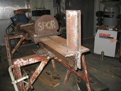
there is a 1" space between them to allow for welding the wedge and
cylinder anchors. (see pic 2342)
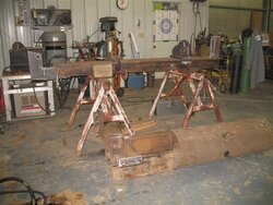
the opposite end where the 5 x 36 cylinder will be mounted (it's not welded
in yet, just has a clamp holding it) will also be welded between the two
angles. (see pic 2340)
every 18" along the beam and between the two angles, I welded a 1" thick x
2" wide x 6" deep piece of stock to help stiffen it up. it's kind of hard
to see from the pics.
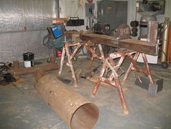
pics 2340 and 2341 shows the 3 point and the hydraulic tank pipe.
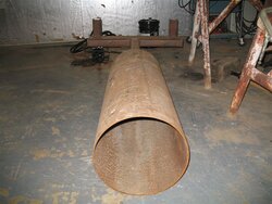
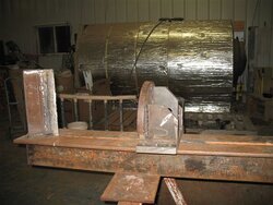
the hydraulic tank is a 1/4" thick x 16" dia pipe x 48" long. (see pic
2344)
I will be using a L4400 Kubota's PTO to run a 22 GPM pump.
questions I have are:
1) can I weld the bottom of the beam to the top of the 3 point and pipe?
2) when splitting a chunk of 30" long elm, will the beam have too much
twist and pull the welds form the tank and beam?
3) do I need to weld a plate, say 5/8" or 3/4" thick x 8" wide x the length
of the beam on the bottom and then weld the tank to that plate, or will the
tank be strong enough without the added plate?
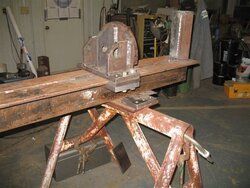
4) referring to pics 2343 and 2345, is the wedge and push plate strong
enough?
the wedge is made of 1" thick x 6" wide x 18" long (6" of this is between
the two angles).
I then beveled, hard faced and reground the point.
two angles 3/8" x 3" x 3" x 12" were welded on both sides of the wedge to
strengthen the wedge and help separate the wood while splitting.
the push plate is mostly 1" thick material.
5) I think I may have already drilled the hole for the cylinder on the push block mount too high.
it measures 5" off of the top of the beam. when I mount the cylinder on to the puch block, there will be a 2" gap between the bottom of the cylinder and the top of the beam.
the farther the cylinder is mounted off of the beam, the more twist I will have ... correct?
do you think it will be ok, or do I have to cut the push block apart and reposition the hole so I only have... say 1/2" of space between the bottom of the cylinder and the top of the beam?
I hope you can help me out so I don't have to do too much rework.
thanks,
topo
 

Attachments

  • IMG_2340.jpg
    IMG_2340.jpg
    60.5 KB · Views: 1,303
  • IMG_2341.jpg
    IMG_2341.jpg
    60.1 KB · Views: 1,293
  • IMG_2342.jpg
    IMG_2342.jpg
    54.4 KB · Views: 1,602
  • IMG_2343.jpg
    IMG_2343.jpg
    58.5 KB · Views: 1,397
  • IMG_2344.jpg
    IMG_2344.jpg
    51.1 KB · Views: 1,232
  • IMG_2345.jpg
    IMG_2345.jpg
    54.8 KB · Views: 1,691
I envy your tools, your shop & most of all your skill. One suggestion I would make is that the base of your push block be made longer. (I assume you are using grade 8 bolts) Back in the 1970s I had a splitter with a 5" piston with a large single stage pump from a garbage truck. Used a Wisconsin V-4 engine for power. I was splitting an elm crotch one day & busted every thing loose. The ram was 10" c-channel with gussets on the back like yours. Before I could get my hand off the control, I busted the gussets loose & laid the channel almost flat to the beam & snapped most of the bolts. Like you said, you've also got the piston sitting high which will stress everything even more.

You are building a serious piece of machinery! how are you going to move it around? Since it is horizontal only, will you be putting a log lift on?
Good luck
l
 
I would reposition the cylinder to get it as close to the beam as practical, ~1/2" is good - this will reduce the stress on all the parts.

I think all beams will flex a little under load, I'd try to keep the tank isolated from the beam to avoid stressing it at all and possibly cracking a weld over a long period of time... If you do need to weld the tank to the beam, I'd only fasten it in a couple of places, not try to do a continuous weld that would make the tank a stressed member of the beam...

Gooserider
 
looks like an interesting project
nice shop
just wondering, arc or mig ?
maximum penetration into that thick metal with arc - correct ?
dont want those welds tearing out
rn
 
I would add square blocks under the flange under the wedge.
 
Thanks for the replies.
Rusty nut, I tack weld the parts using 7018 and do the finish welding using FCAW on all of the heavy plate.
I use MIG on the thinner material like the ends of the hydraulic tank and the hose connections to the tank.
Lobsta, I’ll be moving the splitter around with a L4400 HST Kubota tractor that’s about 44 HP. And yes, there will be a power beyond valve with a log lift. I'm still figuring a design for that.
Gooserider, that’s what I thought. I built the push block prior to getting the cylinder and I didn’t want the cylinder too low, but I guess I have it too high. I will lower it so there’s only ½” between it and the beam.
Damn, I hate rework.
Do I need to put a “U” clamp on the push end of the cylinder, or will it stay straight when it’s extending? It’s a 36” extension.
Solar, I plan on welding a 5/8” plate on the wedge end of the beam. Is this what you were referring to?
I would also like to add a carriage that follows the push block back and fourth so the heavy chunks of wood would automatically return to the start position. I thought I once read a thread where someone built one. Does any one know were I can find the thread?
 
Your Q 3: Yes, number one, I would add a bottom flange to the angles. I don't have steel books here for the I & S factors, but I am guessing you will make it probably 4 to 6 times stiffer (less deflections) and stronger (less stresses) with a bottom flange equal to the top ones. Angles are not real strong in bending and tend to twist because they are not symmetrical shapes. The more metal is, and the further it is out from the center/neutral axis, the better. Stiffness is a cube of depth, so doubling depth makes a beam 8x stiffer. Stresses/strength are a square term, so 2x the height = 4 times the strength or 1/4 the stresses.
Best of all would be to add two more angles, just like you have, making it 12 inches high with the 4 inch flanges on the bottom. Sounds like overkill, but 5 bore is a lot of force and bending, especially if you think the cylinder is mounted uup high away form the beam. I can't see a cylinder. Probably simplest also to just add angles.

Stiffener blocks vertically under the angles don't do much. They don't help the main beam made of the angles in bending or in torsion, only in keepng the flange from bending up or down by the reactions of the push block. I would not take them out, but they are really just dead weight.

5 inch cylinder, from tracto hydr, will be REALLY slow and a lot of force. How will your tank hook up to tractor hydr, or will you have a PTO powered separate pump? edit: saw that you said pto 22 gpm pump. nice match.

Yes, I think it will flex the beam a lot. for that size of cylinder, you need some more beam.

No I would NOT weld the tank to the beam. More complicated to explain why, but basically the stiffness of the beam is more than the stiffness of the tank, so the tank adds no strength to the beam, it will just bend and flex. I think it will soon crack the pipe wall loose from the beam. Also, any flexing of a hydr tank keeps releasing mill sclae and rust and junk into the oil. Best to have the tank totally de-coupled from any loads.

kcj
 
I think the push plate is to wide and will put a lot of side force to it if you have an angled piece. I would weld a 1in x2in xheight of push plate in the middle so it will keep the force in the middle of the push plate. I would also think about making a movable 4 or 6 way wedge to use all that power.
leaddog
 
Yep. Isolate the tank but I don't believe in rebuilding until I'm sure that what I have won't work.
Go with it, leaving room for improvements & or changes.
That 5/8" angle is some pretty beefy stuff and may well hold up to 5" cylinder.
Go with confidence.
 
topofthehil said:
Solar, I plan on welding a 5/8” plate on the wedge end of the beam. Is this what you were referring to?

Yes, something to keep the end of the beam from twisting. A 5 inch cylinder and a wide wedge are going to put some loads away from the center of the beam unless you are only splitting straight grain rounds.
 
Kevin, I wish I had more of the 5/8" x 4" x 6" angle, but as it is, I am short by about 4", so I will need to fab an extension on the cylinder mounting end. the beam's 93" and I need 97". I think I will weld a piece of 5/8" x 8 " wide x the length of the beam to the bottom of the beam and pray this will stiffen it up enough.
I agree with the comments about not using the tank as a stiffener.
I think I'll somehow strap the tank to the bottom or side.
Leaddog, after testing the splitter with some elm to make sure it can handle it, I may make a 4 way to slip over the single wedge.
I don't follow your suggestion on the 1" x 2" x height of base plate addition?
the base plate measures 1" thick x 6" wide x 13" long. I am stuck with the 13", as this is a fixed dimension.
the 1" x 6" width is all I had for material. are you saying it should be more than 6"?
thanks,
 
topofthehil,
been out for a while
FCAW ?
was that flux cored mig ?
rn
 
rustynut, yes FCAW is flux cored arc welding. like the MIG solid, but better penetration and very easy to weld vertical up with. I use the gas shielded (75 Ar/25 CO2) type E71T-1, so I can go out of position. that chunk of steel I am welding together is getting to be too heavy to swing around in the flat position. I have the material to build a mobile lift/hoist, but just can't find the time to do it.
 
Got back to work and checked my steel book. Assuming 2500-3000 psi, 5 inch bore cylinder, 6 inches above top of the beam, it would fail in compression of the bottom of the beam. About 150-200% of allowable yield, not including fatigue considerations.

The doubling of angles was overkill as I suspected. Takes the strength to about 2 or 3 times what is needed. I tossed it in because it would easiest.

I ran adding some flats to the bottom. Funny, your plan to add 8 inch x .625 flat was one of what I was going to suggest here. That would handle the cylinder force as high as 10 or 12 inches off the surface of the beam (or to put it another way, a 12 inch high wedge with force at top, which is how it should be designed). Failure would eventually be at the top flange in tension, beyond the loads you are putting on it. That is a great solution if you have the material, and makes it symmetrical.

Not sure what you mean by plating under the wedge. If you mean adding a flat along the web, it won't help much. Adding metal doesn't do much to strengthen when it is an open section in torsion (rotating along the long axis of the beam, by the top of wedge trying to twist the beam)
You need to get to a closed box section to stiffen it. If you mean from outer edge of top flange to outer edge of bottom flange, great. That boxes it into a closed section. Moving that flat in a couple inches allows the slider to grab the flanges, but still make it a closed box section. That should go full length not just by the wedge. Part length will help, as it carries the stresses out into the flanges more, but full length would be best. Else it twists in the remaining open section.

To illustrate the difference between open and closed sections, try this experiment:
-Take a piece or printer paper. Hold the 8-1/2 inch ends, one in each hand. Twist back and forth, along the long direction to simulate torsion of the 11 inch long ‘beam’ model. Easy to twist.
-Roll the paper into a tube, maybe 2-1/2 inches in diameter and twist it again. No change, still easy to twist.
-Roll it into a one inch diameter tube. Twist again. Still easy to twist in torsion.

This sort of illustrates an open section is weak in torsion. Really doesn’t matter how a given amount of metal is shaped. Using thicker paper will help some, like your added flat to the web, but only a small amount.

-Now, put three short pieces of scotch tape on the seam along the outside of the coiled up one inch tube. The tube is made into a closed section with a few ‘paper tack welds’ that resist shearing. Twist again. Much stiffer in deflection and stronger.
-Try the 2-1/2 inch diameter version, with tape ‘welds’. It will be much stiffer than the open section 2.5 inch, and stiffer than the closed section 1 inch diameter.

So, for something in torsion, getting a closed section of the largest size possible gives the stiffest construction. Not necessarily strongest, but the most rigid. The difference between stiffness and strength is another topic.

k
 
K, so, what you are saying is I can leave the cylinder mounted where I have it? if I mount the cylinder on the push block, there is a 2" gap between the bottom of the cylinder and the beam. it would be great if I did not have to redo this. as it is now, the cylinder mounts to the center of the push block. is that too high?
what's an ideal height for the cylinder to be mounted to the push block... just below center, center or just above center?
If I weld the 5/8" x 8" x length of the beam to the bottom of the bean, do I need to "box in" the beam, or would it be over kill? I currently have a 1" spacer between the two angles that kind of act as a box.
allowing for the under bolting of the push block, I would only get about a 1-1/2" box on each side.
if you think I still need to "box in" the beam, would 3/16" or 1/4" be heavy enough?
this splitter's getting to weigh a ton as it is. well, maybe not a ton, but it's going to be interesting to weigh it when I'm done building it.
tks, topo
 
Qwhat’s an ideal height for the cylinder to be mounted to the push block… just below center, center or just above center?Q


Ideally? The cylinder centerline should be directly in line with the force in the wood to minimize the moments (rocking) on the slider. If the cylinder force is above the resisting force of the wood, the slider will tip forward. The front of the slider pushes down against the top of beam, and the rear of the slider lifts up against whatever grips under the beam flanges.
More likely, if the cylinder force is below the wood force, (the force is at the very top of wedge and very top of slider) the front of slider lifts up and rear pushes down. So it all depends on where the forces are. That varies from split to split, and probably through any given cycle. With larger rounds, the forces will be greater and higher up on the wedge/plate. Structurally, I design for worst case, which would be the entire tonnage applied to top of wedge and top of slider.
So it depends on your crystal ball. I would set the cylinder center line about 50 or 60% of the way up the wedge height, but there is no magic there. If you are roughly half way up I’d finish the build and run it.


Q If I weld the 5/8” x 8” x length of the beam to the bottom of the bean, do I need to “box in” the beam, or would it be over kill? I currently have a 1” spacer between the two angles that kind of act as a box.Q

Probably not. You will have plenty of bending strength in the beam from adding the 5/8 at bottom. Boxing would be to stiffen the torsion/twist in the long direction. That is usually not a permanent yield issue, just a flex and spring back issue, so I don’t think there would be any permanent damage if it was too soft. So I’d add the 5/8 x 8 on the bottom and try it. You can always add boxing later. Note: you would only see the torsion when in nasty crotch wood that puts a side load on top of the wedge, trying to twist the beam. You might go a long time without ever having that condition.

I would add some vertical blocking, from under the top flange to top of bottom flange, at the rear of the wedge to stiffen the top flange. Basically a plate at the end of the angles you have shown. As the wedge tries to bend left or right, it will push down or lift up on the top flanges. Vertical blocking there will tie the top flange to the web and to the bottom flange. That is not to counteract torsion of the entire beam length, but to stiffen the top flange only.

Q if you think I still need to “box in” the beam, would 3/16” or 1/4” be heavy enough?Q

Gut feel, without any calcs, yes it should be plenty to resist torsion. If you were making a box beam without the center web created by the legs of the angles, then the side plates would take more thought. Here, the center carries the bending, and the boxing would only resist the shearing action from torsion, so it doesn’t need to be very heavy. You can save weight by cutting 6 inch diameter holes along the mid point of the plates, like a bridge or crane girder. Steel at the center of the boxing is not important. The boxing resists shear like the scotch tape welds in the experiment I posted before.

I think you are on the right track. The main change was adding the bottom flange. That is a huge difference. Cylinder location is a minor effect. I’d continue the build, add the bottom flange and plate on the end, and get it pushing to try it.


k
 
kevin,
thanks for your help. the splitters on hold for a week or two. I need to buck some elms out of the bottoms before the snow gets to be a problem. I have a lot of dead elm, but I also have a lot of steep hills to navigate. sorry to say, I cut this years wood for this years burning. thank God for dead elm. I have oak and hickory I could cut, but I just can't find the time to cut a year in advance.
 
relate to that. Usually scrounging dead elm as I like to burn it, there was a lot around here, and I don't have much storage. whateveer is free......
good luck kcj
 
I finally got back to working on my splitter.
I am at the point where I could use so some help plumbing multiple valves on the splitter.
at first, I just needed a valve for the splitter, then I thought that a log lift would be nice, so I bought a power beyond valve. now, I would like to add a 4 way adjustable wedge.
I currently have a Prince 5000 power beyond valve to run the lift and a Prince 3000 valve to run the splitter.
the first question I have for you is how do I connect the power beyond valve to the next valve?
hard pipe, and if so what schedule?
should I use unions?
do I have to buy another power beyond valve for the 4 way adjustable wedge?
do I use power beyond valves for every valve but the last one?
I assume the last valve is the splitter valve?
what kind of pressure does the return lines see?
what can I use for plumbing the return line from the valves to the hyd tank?
can this be sch 40 fittings from the valve to the hyd tank?
thanks for your help.
 
Not sure about the rules on picking multiple valves, but in terms of plumbing, remember that the input side of each valve will be seeing full hydraulic system pressure - potentially up to 3,000PSI, so you do NOT want to use schedule 40 to connect them... Use the appropriate high pressure rated hardware. I don't see a great need for unions beyond whatever you need to be able to take things apart w/o excessive difficulty, which is the general rule for unions in any case...

OTOH, the return lines going back to the hydraulic supply tank are at only slightly above atmospheric, so you can use schedule 40 pipe and normal oil lines for the return side plumbing. However I have had the rubber line on a barb w/ hose clamps blow off, which is a MAJOR mess maker, and can drain the oil tank and run your system dry in just a few seconds (w/ resulting pump damage) so I STRONGLY recommend using manufactured hose assemblies w/ low pressure hose for the return side - the peace of mind it gives is worth the extra cost...

Gooserider
 
Goose is on it - all valves are going to need high pressure lines until the last one of the system. That will be the ONLY valve that you can use low pressure stuff on the return line. In power beyond valves, the output (return) of one valve can/will be the input (pressure) to the next valve.
 
thanks for the advice, but what should I use ... sch 80 and a union, or is there a short piece of hyd hose with swivels that is made just for going from one valve to the next?
is the power beyond a NPT or do I use boss type fittings like on the cylinder?
 
Take the components to a shop that will build you some hoses. Most farm implement stores do this as well as places that deal with industrial equip. They can not only build what you need, but answer any questions specific to your components (like fitting type, etc).

Edit: or if you can get Kevin's attention again, sit back and listen to what he has to say. ;-)
 
thanks for the advice.
I bit the bullet and bought a two spool valve with a bypass. that way, I only have to plumb two valves together when the time comes to add the 4-way splitter.
this thing (splitter) is getting to be rather heavy.
I did a test lift with the tractor and slightly bent the lifting link support. so, I plan on beefing that up.
I may have to add some type of wheel to help support the end if the beef up doesn't remedy the problem.
or, stick an axle under it and make it a pull behind.
once I figure out how to post pics, I'll do so.
I had help with the first set of pics.
 
Status
Not open for further replies.