Gooserider said:
so that your fossil boiler won't try to heat the storage or wood boiler, and the wood won't try to heat the fossil boiler...
Gooserider
Unless of coarse you want to do it that way.
")
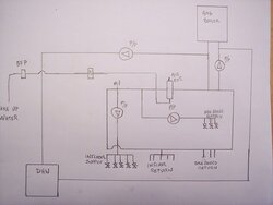
I did it as described by gooserider( what not to do ) for my own reasons warped as it may seem but works just fine and is accomplishing my goals..
If I have my OWB filled and burning, the water eventually flows thru the oil burner keeping it shut down as the water is hotter than the settings. The oil burner being warm when called into service , fires easily. (oil burners don't like cold starts) especially with non traditional oil.
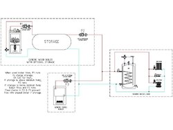
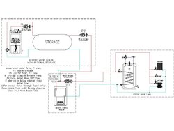
When the OWB is running full throttle it has the capability to heat my storage tank, and oil burner and my Primary secondary loop.
When the fire dies in the OWB the WMO boiler heats the storage and the non firing OWB Which at this point is nothing but 275 gallons of storage.
At any given time my whole system is above 140 * with one or the other heating the water to prevent any freeze ups.
I normally fill the OWB every 12 - 14 hours have gone 24 hours before re fill.