New Boiler Installation- Any help would be greatly appreciated- NEW PICS

  • Active since 1995, Hearth.com is THE place on the internet for free information and advice about wood stoves, pellet stoves and other energy saving equipment.

    We strive to provide opinions, articles, discussions and history related to Hearth Products and in a more general sense, energy issues.

    We promote the EFFICIENT, RESPONSIBLE, CLEAN and SAFE use of all fuels, whether renewable or fossil.
Status
Not open for further replies.

NewBoiler

New Member
Feb 23, 2010
45
Canada
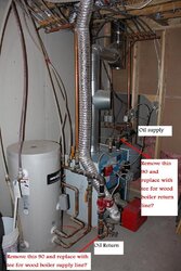
I currently have a Slant/Fin oil boiler installed in one side of my basement. It has 5 zones, one for indirect hot water tank, one for garage using baseboard, one for basement using cast iron rads, one for main level using cast iron rads and one for 2nd floor using baseboard. All components (except indirect water tank- Black iron pipe) are connected using 1/2" hepex plastic tubing.

I am planning on replacing my wood stove with an indoor conventional wood boiler, specicially Kerr TW2000. The wood boiler will be installed on the other side of the basement where the masonary chimney is located. The distance is about 47 feet from the exiting oil boiler. I'll obviously need a supply and return line running from the oil boiler to the wood boiler. The manual says that the supply/return lines cannot be plactic tubing. Is this correct? Do I need to use black iron piping to go that distance in the ceiling?

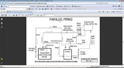
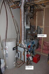
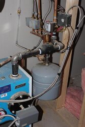
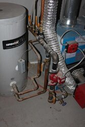
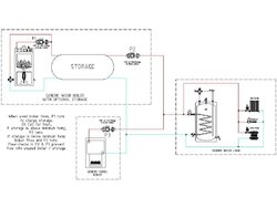
I'll post some pictures of the existing oil boiler and its setup, so I can get some help on where to connect the supply and return lines. I believe I will be going with a parallel setup as the attached diagram shows from the Kerr manual. The question is, can I use the existing circulator pump and expansion tank? or do I need to install addtional for the wood boiler?

I'll get pictures tonight and specs on my expansion tank and existing circulator pump.
 

Attachments

  • kerr_parallel.jpg
    kerr_parallel.jpg
    55.3 KB · Views: 1,327
OK, here are some pics of the current boiler setup. Where would I tee in the supply and return from the wood boiler?? 1st pic is of total system, 2nd pic is of supply and 3rd pic is of return
 

Attachments

  • IMG_2939.jpg
    IMG_2939.jpg
    111.1 KB · Views: 1,072
  • IMG_2940.jpg
    IMG_2940.jpg
    92.4 KB · Views: 1,046
  • IMG_2941.jpg
    IMG_2941.jpg
    99.1 KB · Views: 1,019
Oops didn't realize I already had the New_Burner account on this computer, I'll continue to use the NewBoiler account.
 
The only hitch I see with your proposed connection plan is the lack of some kind of zone valve/check valve for the oil boiler. If your oil boiler is off, wood boiler on, you want to make sure the supply from your wood boiler doesn't simply run through the oil boiler and back through to return. Your flow will always take the path of least resistance. Is there something internal to the oil boiler that prevents flow when it is not on?

Zone valves are pretty easy to use to accomplish this kind of control if you need it. If not, your plan looks very simple and straight forward.

One observation - it sure would have been nice if your oil boiler would have been installed with a union on the supply side. That could be pain unless you simply cut that straight piece right down the middle. Still going to take some work...
 
Also, I think you have your supply/return backwards on your edit's. Your wood supply needs to tie into the same line as your oil supply...not reversed...
 
Thanks for the comments...Concerning the supply /return,if you look at my first post that shows the manual's diagram, the woods return id tied into the oils' supply and vice versa....your right though, opposite what I would have thought.
 
That factory drawing makes absolutely no sense to me - it appears to be running some sort of short circuit loop through the oil boiler, or possibly a Primary / secondary loop through the Oil boiler, does not look like a good design at all IMHO...

I've stuck up a drawing I did a while back that shows a reasonable generic parallel hookup - note that the supplies from both boilers go together, as do the returns. You will get NO flow through the unused boiler, and the rest of the system is unchanged...

Hope this helps...

Gooserider
 

Attachments

  • parallel-w-pumps.jpg
    parallel-w-pumps.jpg
    68.7 KB · Views: 1,088
A friend of mine has his New Yorker plumbed this way, and I believe it is setup like that to keep the oild boiler at a certain temp. Then when the zones ask for heat, the oil boiler doesn't turn on, the zones just open up.
 
The diagram below shows the factory setup for a Benjamin wood boiler (i was also looking at one of these), and it shows what Gooserider was talking about, supply from both boilers together and return from both boilers together.
 

Attachments

  • DO110_Plumbing_-ENG.jpg
    DO110_Plumbing_-ENG.jpg
    91.8 KB · Views: 7,396
you should buy a tarm and not a tw2000, that's what i have and not happy with it. but it is only my opinion.
the tw2000 is cheap but take lots of wood. :(
 
The first diagram you posted is called a series hookup. This should be avoided at all costs! The problem with a series hookup is that the hot water from the wood boiler mixes with the cold return water from zones and reduces the available temp to heat. It drops by about 10* per zone that is running. Installers like this hookup because it requires few controls and allows a fossil boiler with a DHW coil to stay hot enough all the time to provide DHW.

The second diagram is a parallel hookup with reverse flow through the fossil boiler. This is an okay hookup. When the wood is hot the water can go directly to zones and if no zones call for heat, it reverses through the fossil boiler keeping it hot. The advantages of keeping a fossil boiler hot are that it can provide DHW via a coil in it, it won't experience thermal shock of having to come up from stone cold when heat is called for, and there is less expansion/contraction of gaskets. The disadvantage is that they are not well insulated and tend to radiate heat reducing efficiency. They also tend to send heat up the stack as well. The second diagram also has an overheat zone with a zone valve that opens incase of power outage (labeled #2).

If you have no need to keep the fossil boiler hot, then you could do a truer parallel hookup which would look like Nofossil's sticky on "Simplest Pressurized Storage System Design". You would just eliminate the storage tank in your case and adjust the zone portion if you have zone pumps instead of zone valves. That is probably the most efficient way to hook it up.

FWIW, I too would recommend getting a gasifier. The extra cost is easily made up in just a couple of years of reduced firewood costs and/or your time and labor over wood. A non-gasser will burn twice as much wood (or more), has the risk of chimney fires (especially in shoulder season), and can't supply DHW in the off season. Just my $0.02!
 
Gooserider said:
That factory drawing makes absolutely no sense to me - it appears to be running some sort of short circuit loop through the oil boiler, or possibly a Primary / secondary loop through the Oil boiler, does not look like a good design at all IMHO...

I've stuck up a drawing I did a while back that shows a reasonable generic parallel hookup - note that the supplies from both boilers go together, as do the returns. You will get NO flow through the unused boiler, and the rest of the system is unchanged...

Does the check valve in P3 stop the flow on the return side? e.g. stop flow in both directions unless the pump is running?

Thanks
 
This is what the Kerr rep sent me about the hookup. Thanks for the information.

"One reason is that so circulators will not be pushing against each other.The circulator on the oil unit is usually the primary circulator for thehouse system.Another reason is the position of the controls in the boilers, we want hotwater returning to the oil boiler so that it will not be starting the burner on a call for heat."
 
NewBoiler said:
This is what the Kerr rep sent me about the hookup. Thanks for the information.

"One reason is that so circulators will not be pushing against each other.The circulator on the oil unit is usually the primary circulator for thehouse system.

It is just a matter of putting the tee in the right place. Where that is depends on whether you have one pump and zone valves for each zone or if you have separate pumps for each zone. Which is it?

Another reason is the position of the controls in the boilers, we want hotwater returning to the oil boiler so that it will not be starting the burner on a call for heat."

This is the great excuse they always give for using the series hookup. You can use an aquastat and relay to keep the oil from firing when the wood is hot instead of their method which results in low temps available for zones.
 
Sawyer said:
Gooserider said:
That factory drawing makes absolutely no sense to me - it appears to be running some sort of short circuit loop through the oil boiler, or possibly a Primary / secondary loop through the Oil boiler, does not look like a good design at all IMHO...

I've stuck up a drawing I did a while back that shows a reasonable generic parallel hookup - note that the supplies from both boilers go together, as do the returns. You will get NO flow through the unused boiler, and the rest of the system is unchanged...

Does the check valve in P3 stop the flow on the return side? e.g. stop flow in both directions unless the pump is running?

Thanks

Yes, the flow-checks in all three pumps (not just P3) serve to prevent reverse flow when the pump is off. Remember the fluid flow is "lazy", and will always follow the path of least resistance from high pressure to low... It will NEVER flow from low pressure to high without a pump... So, if either P2 or P3 is running, the tee at the supply to the house load is under pressure, and the flow check in the non-running pump keeps the flow from going backwards through it. Thus the only path for water flow is through the house load. When the flow gets to the tee on the return side, it can't take the branch into the non-running side, as that would require pushing from low pressure to high, through the non-running pump and it's flow-check. OTOH, the branch going towards the running pump has a negative pressure on it, exactly equal to the volume being pushed out by the running pump...

I should also note that in the drawing I posted, the storage tank is acting as a hydraulic separator to isolate the wood boiler. If not using storage, P1 would do the same function that P3 does. There are also many other ways that one could do the storage setup, the approach shown is just one of them.

Gooserider
 
Gooserider said:
Sawyer said:
Gooserider said:
That factory drawing makes absolutely no sense to me - it appears to be running some sort of short circuit loop through the oil boiler, or possibly a Primary / secondary loop through the Oil boiler, does not look like a good design at all IMHO...

I've stuck up a drawing I did a while back that shows a reasonable generic parallel hookup - note that the supplies from both boilers go together, as do the returns. You will get NO flow through the unused boiler, and the rest of the system is unchanged...

Does the check valve in P3 stop the flow on the return side? e.g. stop flow in both directions unless the pump is running?

Thanks

Yes, the flow-checks in all three pumps (not just P3) serve to prevent reverse flow when the pump is off. Remember the fluid flow is "lazy", and will always follow the path of least resistance from high pressure to low... It will NEVER flow from low pressure to high without a pump... So, if either P2 or P3 is running, the tee at the supply to the house load is under pressure, and the flow check in the non-running pump keeps the flow from going backwards through it. Thus the only path for water flow is through the house load. When the flow gets to the tee on the return side, it can't take the branch into the non-running side, as that would require pushing from low pressure to high, through the non-running pump and it's flow-check. OTOH, the branch going towards the running pump has a negative pressure on it, exactly equal to the volume being pushed out by the running pump...

I should also note that in the drawing I posted, the storage tank is acting as a hydraulic separator to isolate the wood boiler. If not using storage, P1 would do the same function that P3 does. There are also many other ways that one could do the storage setup, the approach shown is just one of them. Gooserider

Thanks Gooserider, your explanation clears my mind on f/c pumps and will make my designing a lot easier.
 
Gooserider said:
Sawyer said:
Gooserider said:
That factory drawing makes absolutely no sense to me - it appears to be running some sort of short circuit loop through the oil boiler, or possibly a Primary / secondary loop through the Oil boiler, does not look like a good design at all IMHO...

I've stuck up a drawing I did a while back that shows a reasonable generic parallel hookup - note that the supplies from both boilers go together, as do the returns. You will get NO flow through the unused boiler, and the rest of the system is unchanged...

Does the check valve in P3 stop the flow on the return side? e.g. stop flow in both directions unless the pump is running?

Thanks

Yes, the flow-checks in all three pumps (not just P3) serve to prevent reverse flow when the pump is off. Remember the fluid flow is "lazy", and will always follow the path of least resistance from high pressure to low... It will NEVER flow from low pressure to high without a pump... So, if either P2 or P3 is running, the tee at the supply to the house load is under pressure, and the flow check in the non-running pump keeps the flow from going backwards through it. Thus the only path for water flow is through the house load. When the flow gets to the tee on the return side, it can't take the branch into the non-running side, as that would require pushing from low pressure to high, through the non-running pump and it's flow-check. OTOH, the branch going towards the running pump has a negative pressure on it, exactly equal to the volume being pushed out by the running pump...

I should also note that in the drawing I posted, the storage tank is acting as a hydraulic separator to isolate the wood boiler. If not using storage, P1 would do the same function that P3 does. There are also many other ways that one could do the storage setup, the approach shown is just one of them.

Gooserider

My exisitng circulator pump is on my return side of the oil boiler (seen in the picture). In your diagram, I believe this pump would be P3, but that is on the supply side of the oil boiler. Does it matter what side of the oil boiler the P3 pump would be on?
 
NewBoiler said:
Gooserider said:
Sawyer said:
Gooserider said:
That factory drawing makes absolutely no sense to me - it appears to be running some sort of short circuit loop through the oil boiler, or possibly a Primary / secondary loop through the Oil boiler, does not look like a good design at all IMHO...

I've stuck up a drawing I did a while back that shows a reasonable generic parallel hookup - note that the supplies from both boilers go together, as do the returns. You will get NO flow through the unused boiler, and the rest of the system is unchanged...

Does the check valve in P3 stop the flow on the return side? e.g. stop flow in both directions unless the pump is running?

Thanks

Yes, the flow-checks in all three pumps (not just P3) serve to prevent reverse flow when the pump is off. Remember the fluid flow is "lazy", and will always follow the path of least resistance from high pressure to low... It will NEVER flow from low pressure to high without a pump... So, if either P2 or P3 is running, the tee at the supply to the house load is under pressure, and the flow check in the non-running pump keeps the flow from going backwards through it. Thus the only path for water flow is through the house load. When the flow gets to the tee on the return side, it can't take the branch into the non-running side, as that would require pushing from low pressure to high, through the non-running pump and it's flow-check. OTOH, the branch going towards the running pump has a negative pressure on it, exactly equal to the volume being pushed out by the running pump...

I should also note that in the drawing I posted, the storage tank is acting as a hydraulic separator to isolate the wood boiler. If not using storage, P1 would do the same function that P3 does. There are also many other ways that one could do the storage setup, the approach shown is just one of them.

Gooserider

My exisitng circulator pump is on my return side of the oil boiler (seen in the picture). In your diagram, I believe this pump would be P3, but that is on the supply side of the oil boiler. Does it matter what side of the oil boiler the P3 pump would be on?
Not really. The key is that both supplies and both returns go to the same tees respectively, and that there be a check valve somewhere in each boiler loop to prevent reverse flow... It doesn't have to be in the pump, though the in-pump valves have some advantages (often they are free in the box with the pump, usually they offer less forward flow resistance than the discrete valves, etc) and as long as the location isn't bad for some other reason, it doesn't matter where in the loop either the pump or the flow check is. Of course, the design should be sound from other view points as well, such as following the "pumping away" concept that says your pump should always be positioned to pump away from the expansion tank, or "Point of No Pressure Change".

Also, just to be complete on the design theory, you can also do a similar setup with just one pump, by putting the pump in the house loop, and putting a zone valve in each boiler loop - In that case, you would run the pump on any call for heat, and open the zone valve on the "hot" boiler while closing the other one.

Given that zone valves cost about the same as pumps, I like the two pump method slightly better, as it cuts down on hardware, while giving more redundancy - if one pump fails, you can heat with the other one, or even swap the two... This could mean the difference between a "weekend emergency rate" repair call, and a "normal business hours" call...

Gooserider
 
Status
Not open for further replies.