Well that was a nice gift George
")
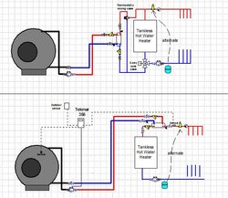
That LA14-50X is already over-sized for your application. I generally design radiant systems around a 15 degree temperature drop across the floor circuits. A 31,000 btu/hr load would require approx 4 GPM of flow. At 4 gpm your HX will introduce less than a foot of head loss so yes you can get away with only the boiler pump by putting the HX in series in the supply piping.
But what is the existing boiler George? Did you mean tankless as in it has a tankless domestic hot water coil. If so, neither the configuration you drew and the alternative I suggested will maintain the boiler temperature to supply domestic hot water. Or is this possibly a condensing wall hung gas boiler? Given that you are currently supplying radiant floors and there is no mix down shown on the existing piping maybe that's the case.
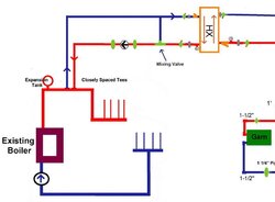
Up until about 15 years ago it was standard practice in this country to put circ pumps on the boiler return line and the expansion tank on the supply side (as yours is shown). Standard practice....but not very good practice, because it sometimes led to air problems with the potential for some locations in the circuit to actually drop below atmospheric pressure so that a small leak or an air bleed fitting could actually introduce air into the system.
Today it is standard practice to always pump away from the expansion tank which is the point of "no pressure change" that Tom referred to.
In reality it's often a matter of how much re-piping you are willing to undertake when you are adding a wood boiler. Ideally when you are operating multiple boilers the boiler that is NOT in operation should not have flow through it but that generally involves more re-piping. I like Hot Rod's solution with the three way zone valve. With a small system like this that's a pretty inexpensive valve.