My thoughts for storage heat transfer

  • Active since 1995, Hearth.com is THE place on the internet for free information and advice about wood stoves, pellet stoves and other energy saving equipment.

    We strive to provide opinions, articles, discussions and history related to Hearth Products and in a more general sense, energy issues.

    We promote the EFFICIENT, RESPONSIBLE, CLEAN and SAFE use of all fuels, whether renewable or fossil.
Status
Not open for further replies.

Lukas060606

New Member
Nov 28, 2010
37
CT Shoreline
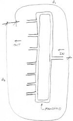
I'm about to get my storage tank up and running. It is going to hold 980 gallons and will be rectangular. My current thought on the heat transfer is have two horizontal arrays of parallel copper pipe with manifolds at each end. One array will be at the top of the tank, and the other will be at the bottom. The two arrays will be connected to each other at one set of manifolds. The manifolds at the opposite end of the arrays will connect to the supply and return. I want the flow through the arrays to reverse depending on whether I am adding/taking heat from the tank. If I am adding heat to the tank, hot water comes in the top manifold, travels through the top array to the other end's manifold, travels down the connector pipes to the bottom manifold, travels through the bottom array to the other end's manifold, and then back to the furnace. When taking heat, the water direction is reversed. I think this is a good design and to me it seems by breaking the flow into multiple horizontal pipes, the flow rate drops and I'm getting better heat transfer. I am also thinking the setup will maximize stratification of the tank. As this is all new to me and a lot of you have been through the trial and error before, please critique my idea. If I'm all wrong, it's obviously better for me to know it now rather than after I fab this thing.
 
There have been a couple of pretty involved threads on this topic over the past couple of years. I think you're on the right general track. I personally went for parallel grids top and bottom with a spiral coil in between. I wish I'd covered the pipes with clip-on copper fins - twice the surface area wouldn't be too much.
 
Thanks for the reply nofo. I didn't know copper clip-ons were available. I'm going to look into that.
 
Lukas060606 said:
Thanks for the reply nofo. I didn't know copper clip-ons were available. I'm going to look into that.

They're not available. But a guy with a log splitter, some copper flashing, and a forming jig could prolly make some......
 
Nice find. That looks expensive. It may be cheaper to just double the number of pipes I'm putting in. Thanks.
 
I'm no expert on flow but water will pass along the route of least resistance. If you use a manifold with a 1.25" header with 1/2" pipes Tee'd off, what's to keep the water moving equally thorough all the 1/2" pipes ? Or, would you be dropping your header diameter down in size as you move farther away from the supply ? So header goes from 1.25 to 1" to 3/4" to 1/2" as you move away from supply ?
 
RobC I'm glad you asked that. I put some time in researching this, and think I found the solution to this issue. The attached sketch shows my plan for the manifolds. The theory being if you add up d1 and d2 for each outlet pipe, the sum of the distances are equal at each outlet. The first time I saw this was on Holmes on Homes where the plumber was installing the DHW distribution. I found the concept interesting and looked into it more and it looks like it works at producing even flow at each outlet. This will be my first shot at using this manifold. If it doesn't work the way I think it will, then I guess I'll scrap it and move on to a plan B. Anyone have any thoughts on this concept?

Another question is about the 1.25" you mentioned. I was actually feeling like a miser and was thinking I could go down to 1" off my 1.25 main piping. I know this is probably penny wise and pound foolish, but getting 1.25" here means I have to go to a plumbing supply store and the markups are frustrating. I thought the 1" would be sufficient, but maybe I should rethink this, bite the bullet, and buy 1.25".
 

Attachments

  • manifold.jpg
    manifold.jpg
    21.5 KB · Views: 341
I’m no expert on flow but water will pass along the route of least resistance.

Precisely.

That's why the water will rather continue on down the 1-1/4 manifold instead of going down any of the 1/2 tubes until the pressure is more or less equal all along the manifold. Then you get more or less equal flows along all the 1/2 tubes. The resistance of the 1-1/4 pipe (per foot) is less than half of the 1/2 pipe.

That's the simplified theory, anyway. With different flows rates and different number of tubes the size of the manifold compared to the exchanger tubes might change. That's beyond my understanding. But this is basically how it works.

The advantage of the multiple parallel tubes/manifold approach compared to the long single tube is much less pumping resistance and energy cost to run the system.

The main disadvantage, I think, is the complexity of all those connections and the cost of all those fittings. Ebay, anyone?

One other design element, no matter which approach you use, is to keep a continual slope throughout the exchanger so air can rise up out of the tubes and not get trapped in a high spot somewhere. That will help make the start-up easier.
 
If you were to Tee 1.25 to 1" that would seem to work especially with the loop manifold. Have you looked at the flow rates, feet per second, going down the 1/2" lines to be slow enough to allow transfer to take place. Here's a link to some pipe size, BTU capacity and flow rates.
http://www.comfort-calc.net/tech_area_index.htm#HWB
 
Tom from Maine, who is in the heat storage tank business, has said that extensive testing showed little benefit from exotic types or shapes of tubing compared to plain copper.

So you might get the most net benefit if you put extra $ into more surface area of plain tubing, rather than special tubing.

I wonder whether anyone has ever tried a turbulator-type device inside copper tubing, in order to break up laminar flow and get more net heat transfer?
 
For 1 1/4" copper pipe, around here Lowe's carries it and a good selection of fittings. I don't know the price difference between Lowe's and a plumbing supply.
 
Before I went with pressureized storage I remember seeing tubing that gave you a turbulator effect by indenting the exterior of the pipe. If you could imaging running your fingers down a length of spinning pipe and gently pinching it.
 
pybyr said:
Tom from Maine, who is in the heat storage tank business, has said that extensive testing showed little benefit from exotic types or shapes of tubing compared to plain copper.

So you might get the most net benefit if you put extra $ into more surface area of plain tubing, rather than special tubing.

I wonder whether anyone has ever tried a turbulator-type device inside copper tubing, in order to break up laminar flow and get more net heat transfer?


My side arm exchanger has a twisted type copper tube in the middle.
 
Status
Not open for further replies.