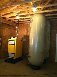
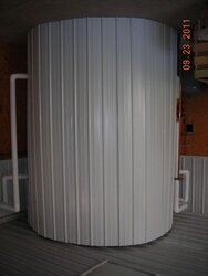
huffdawg said:NYEDGE said:Here's a picture of the vertical install I have.
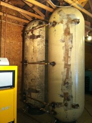
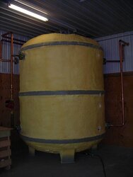
The tanks are new 240 gallon air compressor tanks instead of propane, but a similar outcome.
At the bottom of the tanks I do have a connection that I used to connect a drain line to a valve.
When I drained the tanks after filling and heating, it did let out allot of crud.
I will use them maybe semi-annually to flush out any sediment that has accumulated.
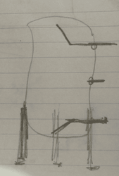
As previously mentioned, try and get all pipes between the tanks the same length so that they will charge and discharge at the same rate.
Are the tanks connected to a primary loop or a series parallel type sytem.
Huff
The tank feeds are in parallel from the wood boiler so that the tanks charge when there is no load from the house. If a zone calls for heat, the zone gets preference.
From the tanks it feeds into the oil boiler with an additional pump and then out to the existing zone manifold including an indirect DHW tank.