
Termovar on supply side
- Thread starter SteveJ
- Start date
-
Active since 1995, Hearth.com is THE place on the internet for free information and advice about wood stoves, pellet stoves and other energy saving equipment.
We strive to provide opinions, articles, discussions and history related to Hearth Products and in a more general sense, energy issues.
We promote the EFFICIENT, RESPONSIBLE, CLEAN and SAFE use of all fuels, whether renewable or fossil.
You are using an out of date browser. It may not display this or other websites correctly.
You should upgrade or use an alternative browser.
You should upgrade or use an alternative browser.
- Status
- Not open for further replies.
jebatty
Minister of Fire
Be sure you're reading the directions correctly. The Termovar to the best of my knowledge always is installed to provide a direct connection between the supply and the return side of the boiler. In essence boiler supply goes to a T, with one leg of the T to the system and the other leg of the T to the Termovar supply side. The return from the system goes to the Termovar system return side, with the remaining leg of the Termovar to the boiler return.
EDIT: Be sure to install a balancing valve between the boiler supply and the Termovar supply fitting.
EDIT: Be sure to install a balancing valve between the boiler supply and the Termovar supply fitting.
jebatty,
The instructions that came with the Termovar are basically the same as http://www.newhorizoncorp.com/PDF/ESBEmixingDanfoss.pdf
which states
So the 160F should be on the supply side - correct?
The instructions that came with the Termovar are basically the same as http://www.newhorizoncorp.com/PDF/ESBEmixingDanfoss.pdf
which states
The 3-way bypass valve shall have a selfcontained non-adjustable thermostatic element
housed within a cast iron construction. The
valve body shall have female pipe thread
connections and shall be installed on a hydronic
heating system. The valve shall be available
with a choice of integral thermostatic elements
with fixed opening temperatures : 160°F (72°C)
for mounting on the boiler supply side; 140°F
(60°C) or 113°F (45°C) for mounting on the
boiler return side. The bypass piping between
the supply and return must incorporate a
balancing valve to ensure proper flow to the
system.
So the 160F should be on the supply side - correct?
jebatty
Minister of Fire
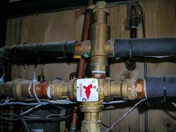
My Termovar has painted arrows with a narrow arrow "in" from boiler supply, a wide arrow "in" from system return, and a wide arrow "out" to boiler return.
Mine is the TERMOVAR 4440A-3
which is "Position 3" oriented at http://www.woodboilers.com/admin/uploads/public/Termovar_Laddventil_ENG.pdf
which is "Position 3" oriented at http://www.woodboilers.com/admin/uploads/public/Termovar_Laddventil_ENG.pdf
jebatty
Minister of Fire
ewdudley
Minister of Fire
SteveJ said:Mine is the TERMOVAR 4440A-3
which is "Position 3" oriented at http://www.woodboilers.com/admin/uploads/public/Termovar_Laddventil_ENG.pdf
This is confusing. The 72 degC valves are normally used in a diverting configuration, 'Position 1', on the supply side. But you have a 72 degC valve that is apparently intended to be used in a mixing configuration on the return side, 'Position 3', which should also have a ThermoBac valve to manage gravity flow and power failure.
But position 3 typically uses a 61 degC / 140 degF valve. However it may be that your vendor has discovered that your boiler performs nicer, cleaner, better with a nice hot 72 degC return and so they gave you the higher temperature valve for use on the return side, which is consistent with the 'Position 3' designation.
Note that the only difference between the positions is the orientation of the functions of the legs of the tee. I wouldn't be surprised if any of the positions could be converted to another by reconfiguring the guts and remarking the label. You might want to look into changing yours around if you go without the ThermoBac and the orientation of the valve is inconvenient for plumbing.
Cheers --ewd
chuck172
Minister of Fire
jebatty
Minister of Fire
Easy to tell. With the valve at room temp, look at the boiler supply side, and you should be able to see that the valve seat is moved towards and probably against the system return side. Look at the system return side, and you should be able to see that the valve seat is against that side. Look at the bottom boiler return and you should be able to see the same things.
jebatty
Minister of Fire
This is confusing. The 72 degC valves ...
72C = 162F which should be boiler return water temp. I have the same valve, and I set the balancing valve so that boiler return is about 145F+/- with really cool system water (< 100F), and as system return rises to about 130F, boiler return will be about 150F+/-. At about 140F system return, boiler return will be about 160F. As system return continues to rise, as in tank charging, and boiler return rises to 160F+, I will almost completely close down the balancing valve to maximize system flow. I don't close down the balancing valve all the way, although I could as system return rises above 160F, because I have forgotten to open it on a new firing more than once.
mole
Member
SteveJ said:Is anybody running the termovar on the supply side rather than return?
I have a 160F, and the instructions say to install on supply side.
Steve, I have the 160F Danfoss mounted on the supply side.
ewdudley
Minister of Fire
jebatty said:This is confusing. The 72 degC valves ...
72C = 162F which should be boiler return water temp. I have the same valve, and I set the balancing valve so that boiler return is about 145F+/- with really cool system water (< 100F), and as system return rises to about 130F, boiler return will be about 150F+/-. At about 140F system return, boiler return will be about 160F. As system return continues to rise, as in tank charging, and boiler return rises to 160F+, I will almost completely close down the balancing valve to maximize system flow. I don't close down the balancing valve all the way, although I could as system return rises above 160F, because I have forgotten to open it on a new firing more than once.
No, a 140 degF mixing valve is typically used on the return side, a 162 degF diverting valve is typically used on the supply side. The OP has what is designated as a 162 degF mixing valve, hence the confusion.
Is your valve 140 degF or 162 degF?
--ewd
mole
Member
SteveJ said:Mole,
Do you have a pic of the termovar install?
Is your circulator on supply or return?
I have the pump on the boiler return. The "under 160" cool return side of the Danfoss feeds back to a T before the suction side of the pump. If you're feeling confused about it, you're not alone. I recall quite a bit of head scratching when I mounted mine, but it all worked out. I can take some pictures tonight if that might help.
jebatty
Minister of Fire
chuck172
Minister of Fire
I've always said the termovar valve is the least understood and most problematic aspect of gasifier wood-boilers.
There should be a detailed sticky on this site detailing this "gadget"
There should be a detailed sticky on this site detailing this "gadget"
jebatty
Minister of Fire
I either was lucky or had a good dealer, who sold the Tarm to me with the Termovar. The dealer marked the ports on the Termovar 1, 2 and 3, as shown in the pictures, and then gave me written instructions on the installation, which I did. Has worked very well continuously, now finishing the 4th heating season.
jebatty
Minister of Fire
I don't know. The threads look more like straight rather than tapered. The union fitting comes with integral isolation ball valves that when closed allow for the removal of the Termovar, and the union does take a male NPT fitting.
ewdudley
Minister of Fire
jebatty said:I have the same valve, and I set the balancing valve so that boiler return is about 145F+/- with really cool system water (< 100F),
[A]s system return rises to about 130F, boiler return will be about 150F+/-.
At about 140F system return, boiler return will be about 160F.
As system return continues to rise, as in tank charging, and boiler return rises to 160F+, I will almost completely close down the balancing valve to maximize system flow.
Just curious, does the Thermovar 161 degF valve control so loosely that it doesn't actually deliver 160 degF return water until it has 140 degF system return water to work with, or is this intentional behavior determined by the balancing valve setting?
jebatty
Minister of Fire
The balancing valve has a big impact on the actual return water temperature. I have a DS18B20 sensor on the return read by a digital panel meter, so I always know what the actual return water temperature is, and then may adjust the balancing valve. Or, I know where I can "set it and forget it," and that setting works well enough so long as system return is not really cool.
I did not realize the termovar control was so loose.
Is there any advantage over a tee in the place of the termovar and a balance valve between the supply and tee?
That is, position 1 in the previously linked PDF with the termovar replaced by a tee...
Seems like the restrictive termovar should have some advantage :bug:
Is there any advantage over a tee in the place of the termovar and a balance valve between the supply and tee?
That is, position 1 in the previously linked PDF with the termovar replaced by a tee...
Seems like the restrictive termovar should have some advantage :bug:
mole
Member
SteveJ said:I did not realize the termovar control was so loose.
Is there any advantage over a tee in the place of the termovar and a balance valve between the supply and tee?
That is, position 1 in the previously linked PDF with the termovar replaced by a tee...
Seems like the restrictive termovar should have some advantage :bug:
Steve,
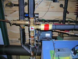
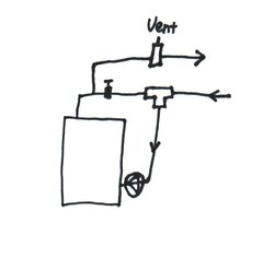
I took some pictures tonight, and need to edit them tomorrow AM to post. My system is a bit different than Jim's. Let me preface by first admitting that I don't have anywhere near Jim's level of experience or expertise, but I want to explain how I installed it and the logic (or illogic) behind my design since there doesn't seem to be a lot of people doing it this way:
I installed the Termovar in "position 1" in the diagram referenced earlier, with the large flow going to the storage tank, the smaller flow to the boiler return. The Seton thermometer indicates that the valve starts to open at 158-160F, which is reasonably close agreement with it's 162F rating. Because of the large thermal mass of the Seton, I've found it best to keep the Seton pump running 24/7 during the burning season, since it can take many hours to cool. (I screwed around with a couple of automatic configurations to start/stop the seton pump, but they didn't work out well). My house heating loop (to a FHA hx and blower) is located between the boiler and the storage tank so when the boiler is running, the heating loop pump draws the hot water directly from the boiler. When the fire is out in the boiler and the house calls for heat, the pump will first pull heat out of the boiler until the temp in the boiler loop drops to 160, closing the Danfoss and isolating the boiler loop from storage loop. At this point, the pump on the FHA loop will pull the hot water in reverse flow from the storage tank. I put it in this way, so that as soon as the boiler has cooled off sufficiently, the first call for house heating will use the Danfoss to isolate the Seton from the storage loop. So it's a simple effective way to prevent heat loss from the storage tank back into the boiler. The reason I put in the 162F Danfoss on the supply, and not the 140F on the return, is because my FHA system doesn't run so well at 140F and I wanted the boiler to be isolated from storage as early on as possible. It works pretty well. I'll try to get those pics up tomorrow a.m.
mole
mole
Member
SteveJ said:Jim,
Thanks for the picture and the orientation drawing.
One question, my termovar did not come with the unions- can you attach directly to female NPT pipe fittings?
Mine took 1-1/4" threaded (NPT) pipe
- Status
- Not open for further replies.
Similar threads
- Replies
- 0
- Views
- 293
- Replies
- 5
- Views
- 724
- Replies
- 0
- Views
- 299
- Replies
- 5
- Views
- 618