Bolier room re pipe & froling install pix-plbg only -- post 1

  • Active since 1995, Hearth.com is THE place on the internet for free information and advice about wood stoves, pellet stoves and other energy saving equipment.

    We strive to provide opinions, articles, discussions and history related to Hearth Products and in a more general sense, energy issues.

    We promote the EFFICIENT, RESPONSIBLE, CLEAN and SAFE use of all fuels, whether renewable or fossil.
Status
Not open for further replies.

skfire

Feeling the Heat
Nov 15, 2010
372
NEPA
Hello All,

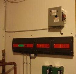
almost done now, we are staring electrical work today.
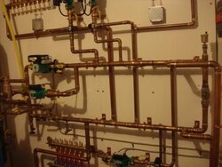
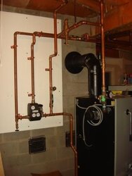
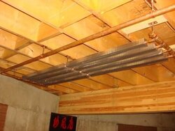
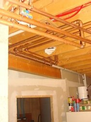
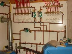
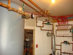
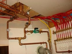
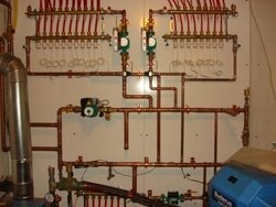
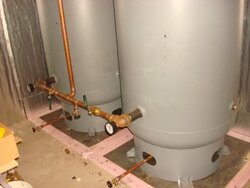
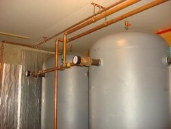
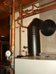
These are some pix(post 1 & 2) of the plbg layouts we finished last week, but started in June..slow go..life takes precedence.

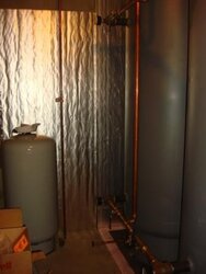
All naked for now, will all be wrapped upon final testing and multiple firings before heating season.

Thank you to ALL IN THIS ROOM...ESPECIALLY RENE @ Tarm, HEATERMAN, JIM IN PA, DUANE, RUSS, KARL K & his brother AND ALL THE OTHER INVALUABLE BOILER ROOM "WRENCHES & BRAINS".
I LEARNED MORE FROM YOU THAN I CAN EVER ACCOUNT AND HOPE TO ADEQUATELY THANK FOR.

Also if it wasn't for Doug and DJS Heating & Brian form TE....this would look...well it wouldn't look like this.

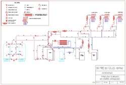
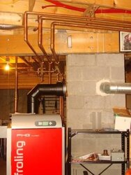
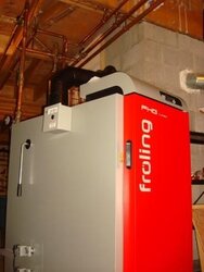
I finally decided on this set up after a long and heavily calculated progress(financial & design/application standpoints).
My original plans were Garn, but certain aspects and values were prohibitive in the end.
Nothing to do with Garn value & quality, just tax, building , trench and location/system issues.
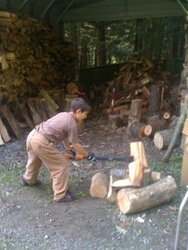
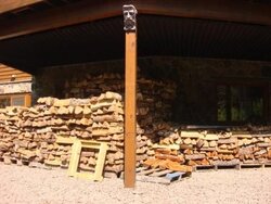
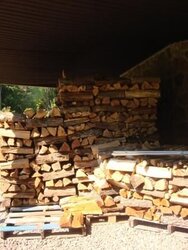
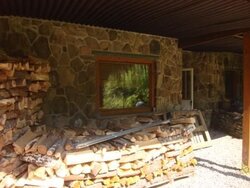
(..as a result, also had to re cut lengths for 6 cords from 26" average down to 13"-21").

More to follow.

Scott

ps: Buderus boiler and indirect are piped for temp, so the wife does not crucify me on the front yard..she may yet ...but the kids are happy...
 

Attachments

  • 1.jpg
    1.jpg
    19.3 KB · Views: 1,419
  • 2.jpg
    2.jpg
    24.3 KB · Views: 1,353
  • 3.jpg
    3.jpg
    23.2 KB · Views: 1,300
  • 4.jpg
    4.jpg
    27.3 KB · Views: 1,324
  • 5.jpg
    5.jpg
    28 KB · Views: 1,361
  • 6.jpg
    6.jpg
    20.9 KB · Views: 1,304
  • 7.jpg
    7.jpg
    24 KB · Views: 1,315
  • 8.jpg
    8.jpg
    26.4 KB · Views: 1,294
POST 2

ADDITIONAL PIX

Scott
 

Attachments

  • 9.jpg
    9.jpg
    17.2 KB · Views: 1,189
  • 10.jpg
    10.jpg
    16.4 KB · Views: 1,231
  • 11.jpg
    11.jpg
    19 KB · Views: 1,201
  • 12.jpg
    12.jpg
    19.4 KB · Views: 1,212
  • 13.jpg
    13.jpg
    23.1 KB · Views: 1,197
  • 14.jpg
    14.jpg
    30.2 KB · Views: 1,205
  • 15.jpg
    15.jpg
    30.3 KB · Views: 1,218
  • 16.jpg
    16.jpg
    28.4 KB · Views: 1,230
looking good !
 
Kudos!
 
Very nice. You'll really enjoy that system.
 
Beautiful looking job Scott. And a great looking home. I was admiring the stonework behind your firewood. I'm looking forward to shots of your installation with the wiring in, particularly where you have most of your pipes and circs after you get that wired. Your photos are providing a great reference (a picture is worth a thousand words). After having to delay my own installation over a year and a half due to a job transfer, I promised my wife our setup would look like yours by Christmas. Plumbing is next. Tough break on having to recut all your logs to length. that must have have been a lot of work. Take care.

Mike
 
2 - vert 400g air receiver tanks for storage
& 1 - 110g exp tank.

Scott

huffdawg said:
skfire said:
POST 2

ADDITIONAL PIX

Scott

is that storage or expansion
 
dogwood said:
Beautiful looking job Scott. And a great looking home. I was admiring the stonework behind your firewood. I'm looking forward to and shots of your installation with the wiring in, particularly where you have most of your pipes and circs after you get that wired. Your photos are providing a great reference (a picture is worth a thousand words). After having to delay my own installation over a year and a half due to a job transfer, I promised my wife our setup would look like yours by Christmas. Plumbing is next. Tough break on having to recut all your logs to length. that must have have been a lot of work. Take care.

Mike

Thank you.
stone work by 75 year old French Canadian mason with "yours truly idiot" as a helper!!! That man was a killer!!!

The logs ... rigged up horses, lined them up and let rip. Just lost time from working on next's years loads, which I made up....sneak out before they wake up and disappear in the woods..come back and act the fool!!! Just kiddin' of course...my son is almost 9 and he started splitting this summer(under my very close watch and instruction....he will be a great helper..the little one is only 5 and she is hell bent on stacking with me.....cute as a heck. It is all because and about them....for me anyway.

Scott
 

Attachments

  • 111.jpg
    111.jpg
    25.5 KB · Views: 987
Sounds like you've got a great family Scott, and are providing for them well. If you're ever out Virginia way I've got some work for both your children out in my woodpile.

Mike
 
Thank you but,
Be careful what U wish for....we are like locusts....:bug:

We actually pass through Shenandoah once a year on the way south...

Scott
 
Delayed by hurricanes, floods, no power for 6 days and washed out/eroded roads and aborted vacation in VA...but electrical all done, currently fine tuning back up and heating systems/controls/DHW and getting ready to fire the Froling.

Getting the Aquatrol AQ logic to communicate and automate with the wood boiler/storage has been educational.
Big heads up thanx to Brian from Thomas Electric.

Some pix attached and also my piping only diagram.
SK
 

Attachments

  • 1.jpg
    1.jpg
    25.2 KB · Views: 896
  • 2.jpg
    2.jpg
    11.5 KB · Views: 897
  • sk schematic piping only.jpg
    sk schematic piping only.jpg
    90.9 KB · Views: 2,133
In your second picture posting, your tanks are sitting on insulation and it looks like something else as well. Is it just cement board? Im assuming to act as a heat/crush shield for the insulation?
 
Clarkbug,
these are 1/4" steel plates I had cut.
Sitting on insulation.

SK
 
skfire said:
Clarkbug,
these are 1/4" steel plates I had cut.
Sitting on insulation.

SK

Woah. Thats heavy duty! I was thinking of putting something in between the tanks and insulation, but I hadnt considered steel plate.
 
skfire said:
Delayed by hurricanes, floods, no power for 6 days and washed out/eroded roads and aborted vacation in VA...but electrical all done, currently fine tuning back up and heating systems/controls/DHW and getting ready to fire the Froling.

Getting the Aquatrol AQ logic to communicate and automate with the wood boiler/storage has been educational.

Some pix attached and also my piping only diagram.
SK

Am I missing the boat on the p/s loops? My thought is shouldn't the in-floor returns be within 4 times the dia. of piping? What I see happening here is you will have ghost flows through the in-floor? or the returns might not have enough head to over come the head in the primary loop? Help me understand.
 
Garnification said:
Am I missing the boat on the p/s loops? My thought is shouldn't the in-floor returns be within 4 times the dia. of piping? What I see happening here is you will have ghost flows through the in-floor? or the returns might not have enough head to over come the head in the primary loop? Help me understand.

It looks like the mixing valves for the radiant zones would short-circuit back to the return side of the primary loop through the mixing valve H-C paths and then the thermostats would close off the H sides as the thermostats get hotter, and then no more flow, lather, rinse, repeat.

So with the zone pumps off there's nothing to bring cool flow into the C port to the thermostat in the mixing valves and there would only ever be hot flow into the mixing valve from the H port, which would keep them shut on the H side.

Also there may be IFCs in the radiant loop pumps that are not shown.
 
Wilo Eco Stratos16fx pumps for the 2 radiant manifold zones, with check vlvs after them.

"and then no more flow, lather, rinse, repeat."
??????? sorry missed that...

SK
 
skfire said:
Wilo Eco Stratos16fx pumps for the 2 radiant manifold zones, with check vlvs after them.
Gotta love those pumps. I had a bushel of perfectly good salvaged conventional pumps of various sizes to work with when I was building my system, but for the ten-zone main distribution manifold it seemed to me that the way to do it right and save money in the long run was to spend a couple hundred on a new Wilo Eco rather than use a free conventional pump.

One zone, no zones, six zones, the pump just does the right thing all by itself.
"and then no more flow, lather, rinse, repeat."
???????
Just saying that after H-C port flow has caused the H port to close, the mixing valve might then cool down a little, which would allow a little more H-C port flow, which would heat up the mixing valve, which would shut off the H port, which would allow the valve to cool down, and flow a little more, and then shut itself off, and then cool down...

But duh, none of it matters because the the zone valves will prevent unwanted flow to the loads in the first place. Plus even if there was short-circuit flow through the H-C ports of the idle mixing valves, any active load pump would be pulling the opposite direction and the primary loop swing check would shut that flow off. So never mind.
 
I guess what I'm seeing/saying is that with your returns that far from the supply (secondary loop), that your secondary might not function as good as it should. There could be a considerable pressure diff. between which might not allow the secondary loop to return

cold into the primary like it should? Yep, no ghost flow w/ check valves but pressure diff.
 
Garnification said:
I guess what I'm seeing/saying is that with your returns that far from the supply (secondary loop), that your secondary might not function as good as it should. There could be a considerable pressure diff. between which might not allow the secondary loop to return cold into the primary like it should?

Maybe the poor resolution of the graphic is confusing things? The non-standard check-valve symbol on the right side of the primary loop makes it look like the loop is going counter clockwise, the bump that should be an arrow is actually supposed to represent the hinge of a swing valve.

The primary loop is running clockwise, so the higher pressures would be a points where the load circs are pulling from and the lower pressures would be where the load circs are returning to, so the primary loop circ is to some extent in series with the secondary loops. It looks like it should work fine, but maybe I'm still missing something.

Yep, no ghost flow w/ check valves but pressure diff.
There's positive shut off with the zone valves, so no opportunity for ghost flow.
 
I am sorry bout the bad graphic schematic. I had to convert form AUTOCAD to pdf and down to acceptable size jpg.
Yes you are correct, it is clockwise flow.

Just saying that after H-C port flow has caused the H port to close, the mixing valve might then cool down a little, which would allow a little more H-C port flow, which would heat up the mixing valve, which would shut off the H port, which would allow the valve to cool down, and flow a little more, and then shut itself off, and then cool down…
Now I get the lather. rinse, repeat ..... Very nice metaphor....I will have to "borrow it"....thank you.

Yes the Wilo pumps are hard on the pocket, but well worth it...had a scrap pile with 8 "tacos" and 3 grundfos...and did not even think about it...Wilo all the way.

The zone valves are the main player in the exorcism of ghosts, but Mr Duddley your analysis was quite succinct. Thank you Sir.

But speaking of ghost flows, I am observing a major therosyphoning effect with tanks cold and back up boiler running for any call.
Major movement through the P/L return leg up the #1termovar port, through the #3termovar port and straight to the tanks.
The zove valve and circ are shut off and tested, and isolated and still the ghost haunts...sure seems like thermic syphoning taking place. Hot loves to chase cold.
Thinking of putting in a flow vlv right after port #3, for case of complete autorun, no boiler no heat in tanks. Can't have the LP freak heating up the tanks..

Thank you for your input guys.
Scott
 
skfire said:
But speaking of ghost flows, I am observing a major therosyphoning effect with tanks cold and back up boiler running for any call.
Major movement through the P/L return leg up the #1termovar port, through the #3termovar port and straight to the tanks.
The zove valve and circ are shut off and tested, and isolated and still the ghost haunts...sure seems like thermic syphoning taking place. Hot loves to chase cold.
Thinking of putting in a flow vlv right after port #3, for case of complete autorun, no boiler no heat in tanks. Can't have the LP freak heating up the tanks..
I suspect it involves the leg that ties the two air eliminators together. Not thermo-siphon, but pumped flow. I'm pretty sure you don't need to tie the Bulderus air eliminator to the expansion tank, the whole primary loop storage tank wood boiler assembly is pretty much one big point of very little pressure change.
 
ewdudley said:
Garnification said:
I guess what I'm seeing/saying is that with your returns that far from the supply (secondary loop), that your secondary might not function as good as it should. There could be a considerable pressure diff. between which might not allow the secondary loop to return cold into the primary like it should?

Maybe the poor resolution of the graphic is confusing things? The non-standard check-valve symbol on the right side of the primary loop makes it look like the loop is going counter clockwise, the bump that should be an arrow is actually supposed to represent the hinge of a swing valve.

The primary loop is running clockwise, so the higher pressures would be a points where the load circ are pulling from and the lower pressures would be where the load circ are returning to, so the primary loop circ is to some extent in series with the secondary loops. It looks like it should work fine, but maybe I'm still missing something.

Yep, no ghost flow w/ check valves but pressure diff.
There's positive shut off with the zone valves, so no opportunity for ghost flow.

Yep it is pulling from higher pressure but might be returning to higher pressure too. The whole point of p/s is to keep the pressures separate on each loop but constant to that loop. Thats the point of the supply /return only being 4-6 times the dia. of the pipe apart.

In that 4-6" there is not any noticeable pressure drop unless it is a monoflow tee, valve, etc. If your other loops have bigger pumps that are being supplied off that pri. loop and returning apart, that could cause a flow restriction in the lower pressure loops.

I still am not putting this into words right>..
 

I suspect it involves the leg that ties the two air eliminators together. Not thermo-siphon, but pumped flow. I'm pretty sure you don't need to tie the LP Bolier air eliminator to the expansion tank, the whole primary loop storage tank wood boiler assembly is pretty much one big point of very little pressure change.[/quote]
[/quote]

Spot on..and thank you.
On Saturday morning I was looking at it and realized I had no chk going in that direction...thus creating another s/l with pump flow reversed through the LP boiler Supervent...even though I do not need the exp. for it, I will add the chk vlv negating back-flow through the Svent.

Regarding the pressure differential, I do not see the issue and when all heating zones were ran no problems where detected; but maybe I am missing the point.

Thank you again..

SK
 
Status
Not open for further replies.