ewdudley
Minister of Fire
Sounds like you've never heard of Afraidium! Galvanized in a pressurized hydronic system? That's crazy talk, mister.Franzen105 said:T Just wondering what is wrong with the galvanized.
Sounds like you've never heard of Afraidium! Galvanized in a pressurized hydronic system? That's crazy talk, mister.Franzen105 said:T Just wondering what is wrong with the galvanized.
in hot water said:galvanized is okay in a hydronic system, use a brass fitting if you plan on connecting copper to galv.
But galvanized cannot be used in a glycol system, according to Dow and other glycol manufacturers.
As for the sand bed storage, that was intended to work wirh a solar thermal array. The concept is to start loading the sand bed in the late summer/ fall and flywheel off that stored energy into the winter months. Wisconsin solar guru Bob Ramlow promotes that system in your area.
hr
mr.fixit said:See if this helps Franzen.
") YICKS....
YICKS.... ! Going to drain it in the morning and start over. Perfect timing snowing up here in northwest wisconsin.... Saweet.........
maple1 said:Isn't the Danfoss supposed to output the right temperature? I thought that was its function - not quite understanding why a manual valve would have to be added to make it work right.
Fred61 said:maple1 said:Isn't the Danfoss supposed to output the right temperature? I thought that was its function - not quite understanding why a manual valve would have to be added to make it work right.
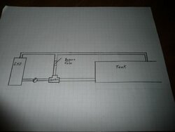
The water flowing through the bypass line is what causes thr thermostat in the Danfoss to actuate. Circulator activates on return pipe and initially pumps water through the bypass line because at that point in time the automotive thermostat is closed. When the water flowing through the bypass line reaches 140 °F or whatever value you installed it flows on to the sensor part (bulb) of the thermostat and causes it to open. Colder water from your heating loop starts entering the boiler mixing with the warmer recirculating water.
Now you have two sources flowing, both tempering each other which more than likely will not allow the thermostat to open much or even possibly close again until the flow from the bypass warms the bulb. When the return water from the system reaches your desired temperature, in my case 140 °F the bulb will sense it and stay open, allowing circulation from the heating loop.
The variable restriction (ball Valve) placed in the bypass line is to limit the flow to your needs. Partially closing it restricts circulation through the loop, allowing more flow from the heat loop. I my case I hit the sweet spot on the ball valve about three years ago and haven't touched it since. Some of it has to do with my set points for circulator actuation but mostly has to do with my heat load or how much heat my flatplate exchanger can transfer into my unpressurized storage tank.
Wanna see how it works. Close the bypass valve completely and the Danfoss will never open.
maple1 said:Fred61 said:maple1 said:Isn't the Danfoss supposed to output the right temperature? I thought that was its function - not quite understanding why a manual valve would have to be added to make it work right.
The water flowing through the bypass line is what causes thr thermostat in the Danfoss to actuate. Circulator activates on return pipe and initially pumps water through the bypass line because at that point in time the automotive thermostat is closed. When the water flowing through the bypass line reaches 140 °F or whatever value you installed it flows on to the sensor part (bulb) of the thermostat and causes it to open. Colder water from your heating loop starts entering the boiler mixing with the warmer recirculating water.
Now you have two sources flowing, both tempering each other which more than likely will not allow the thermostat to open much or even possibly close again until the flow from the bypass warms the bulb. When the return water from the system reaches your desired temperature, in my case 140 °F the bulb will sense it and stay open, allowing circulation from the heating loop.
The variable restriction (ball Valve) placed in the bypass line is to limit the flow to your needs. Partially closing it restricts circulation through the loop, allowing more flow from the heat loop. I my case I hit the sweet spot on the ball valve about three years ago and haven't touched it since. Some of it has to do with my set points for circulator actuation but mostly has to do with my heat load or how much heat my flatplate exchanger can transfer into my unpressurized storage tank.
Wanna see how it works. Close the bypass valve completely and the Danfoss will never open.
I must be slow, I'm still not understanding it. Does the (hot) bypass loop actuate the thermostat, or the (colder) return line? The bolded above seem to be contadictory on that. On the last line, if the bypass valve is opened completely, won't the danfoss thermostatically regulate itself? I thought it worked by sensing the water entering from the return side, and if it wasn't warm enough [say when below 140] it would introduce warming flow from the bypass. Then even if it worked the opposite (sensing bypass temp and [say when above 140] opening the return to introduce cooling flow from the return), I still don't see how manually valving down the bypass flow to it will put more flow through - that would seem to create a situation where you would be trying to direct more flow against what the danfoss would be trying to regulate through itself (making it fight itself?). Maybe I'm just overthinking things.