2 problems: Hydraulic fluid leakage and lots of vibration with my splitter New Pics Posted!!!

  • Active since 1995, Hearth.com is THE place on the internet for free information and advice about wood stoves, pellet stoves and other energy saving equipment.

    We strive to provide opinions, articles, discussions and history related to Hearth Products and in a more general sense, energy issues.

    We promote the EFFICIENT, RESPONSIBLE, CLEAN and SAFE use of all fuels, whether renewable or fossil.
Status
Not open for further replies.

michaelthomas

New Member
Feb 10, 2006
286
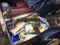
Hello, 2 problems and looking for input on possible causes and fixes.
1. I have some hydraulic fluid seeping from my intake port at my pump. It has a steel 90 degree elbow that has male threads going into the port and is connected to my hose from the reservoir. It seeps to the tune of about 4 oz every 2-3 hours. I cannot tighten it much more because it wont do another whole turn to come around and accept the hose. Can I use teflon tape or something to make the fit tighter?

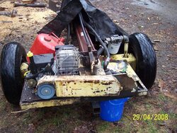
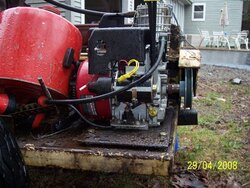
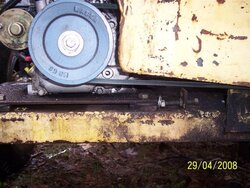
2. My engine is mounted on a thick steel plate and then the plate is bolted to the splitter frame. The engine is an 8 hp B&S;Intek IC horizontal shaft. The engine turns a 4" pulley which runs a belt to turn the pump pulley. The engine has been vibrating so much that the muffler brackets have broken off the engine and the shroud bolts have needed tightening a few times. I am worried about the amount af vibration and my engines longgevity.

When I tighten the belt it tends to get very hot and gives off a burning smell under heavy load, when I loosen it a bit is slaps an inch or so. Could the belt system be causing a-lot of the vibration? Would a direct mount system decrease some of that? Is there a way to mount the engine to absorb some vibration?
 
Leak: You may use teflon tape IF the threads are a tapered pipe thread, and only if. Chances are they are.

Vibration: I've seen Inteks rattle themselves apart on other applications. The mufflers are usually the first to go. They're not really a well built engine IMO.
 
Is the engine kinda hanging out in space on that steel plate? It might need a brace welded on to stop the vibration. You might also have a harmonic that is happening at the exact speed the motor is running. Try adjusting the throttle down a little and see what happens.

I think a vee belt should only be tightened enough to prevent slippage. Most of the time there will be a little play on the slack side when it's running under load. Too tight and you tear up your bearings. We got tired of fighting with the vee belt on the homemade splitter we were borrowing and upgraded to a cogged belt and sheaves. They don't seem to stretch as much and don't need as much tension to transmit the power. This probably won't help with your vibration problem, though.

Try putting some Loctite on the hardware that comes loose and maybe you won't have to do it as often. I haven't been too impressed with B&S;motors over the years either. When you finally get tired of it, look for a Honda GX engine and be amazed at the difference.

Chris
 
A direct pump mount is the way to go if the motor has the proper mounting holes. Newer models have the mounting holes older motors don't. I have a newer 8 hp. Briggs that when I first got it I tried to run it without bolting it down and I had to chase it across the floor. I took it to a Briggs service center. They said it was made for the California market where the emission rules caused it to run rough.
 
triptester said:
A direct pump mount is the way to go if the motor has the proper mounting holes. Newer models have the mounting holes older motors don't. I have a newer 8 hp. Briggs that when I first got it I tried to run it without bolting it down and I had to chase it across the floor. I took it to a Briggs service center. They said it was made for the California market where the emission rules caused it to run rough.

I noticed in the AD for the new Huskee 22 ton splitter I bought that it also "complies with California emission standards". If that makes it run rougher, I wonder what is necessary to make it non-compliant with California emission standards :cheese: . I live in N.Y. so I don't have to go by their laws. If I can change something and make it run better I'd like to do that. I wonder if anyone has done that on here, or looked into it.
 
MT - yes, you can use Teflon tape on tapered threads with hydraulic systems. Some people report on better luck using the pipe dope, your call.

Motor vibration: stiffen the mounts, B&S;motors are not "balanced" all that well and should have a rigid mount. If any "bounce" is allowed, it WILL get amplified when the motor is running. For most pump applications for log splitters, a direct mount is preferred, using love-joy connections. If you do not have the proper mount bolt patters and such, Norther Tool sells a pump mount bracket specifically for this application. But get that motor secured or its just gonna continue to cause problems. A single angle bracket may be all that is needed.
 
Michael, I'm not sure what pump you're running but I was advised to avoid any belt/pully arrangement when I built my splitter. I was told that most 2 stage pumps typically are not designed to handle the side load they see when used with belt drives. I'm no pump expert but by looking at a few pump assembly diagrams I'd have to agree, get rid of the belt or you may be replacing your pump. Lastly, have you tried putting a piece of rubber sheet between your engine and its mount? From my experiences almost any B&S;will rattle the fillings out of your teeth but reducing the vibration into the rest of the splitter shouldn't be too tough.
 
Bracing the mounts is step one as suggested above. That may drive the vibration back further into the structure and cause welds to crack, etc. but I would start there. The wider out the supports and braces, the less force they have to resist.

Sheet rubber helps, but is not too effective as an isolator. Unless the stiffness happens to be tuned just right by coincidence, it is usually too stiff of a mount.
I have used vibration isolator mounts, Grainger 5XK44 is a common, two piece, center bonded mount, that use a ¾ inch hole in the base, 3/8 bolts for motor mounting. (4) required, about $4 each. These are quite stiff for the weight of a 5 hp engine, but are the smallest Grainger had in stock. With steel through bolt and sleeve, and washer on both sides, the engine is positively restrained in case of rubber deterioration. Simple to use: Just drill out the original motor mount holes in the splitter to 3/4 inch, deburr and install. Raises the engine slightly. My 18 hp engine is more in the weight rating and the mounts are quite effective. I used the mounts between engine and power unit frame, and also between power unit and trailer frame. Makes a sweet and quiet running package.

V belts add side load to the bearings and usually not recommended. Make sure the pulley is as close as possible to the pump face. Even fractions of an inch out increase the bearing loads. Tooth belts require less intial tension, but the same added pull to trasmit power. Larger the pulley diameter the less the belt tension and less the bearing loads. If you can change to direct mount, I'd do that rather than put money into timing belts or larger pulleys.

Is the pulley setup used to increase or decrease pump speed? Direct mount would change the required torque and also the output flow. Need to check that first. And, is the pump facing towards or opposite the engine? Will the rotation direction be affected by chainging to direct drive? Obviously pump must turn the same direction...

I'd start with adding braces and adding vibratioin isolators and aligning the belts and pulleys well.

kcj
 
kevin j said:
Bracing the mounts is step one as suggested above. That may drive the vibration back further into the structure and cause welds to crack, etc. but I would start there. The wider out the supports and braces, the less force they have to resist.

Sheet rubber helps, but is not too effective as an isolator. Unless the stiffness happens to be tuned just right by coincidence, it is usually too stiff of a mount.
I have used vibration isolator mounts, Grainger 5XK44 is a common, two piece, center bonded mount, that use a ¾ inch hole in the base, 3/8 bolts for motor mounting. (4) required, about $4 each. These are quite stiff for the weight of a 5 hp engine, but are the smallest Grainger had in stock. With steel through bolt and sleeve, and washer on both sides, the engine is positively restrained in case of rubber deterioration. Simple to use: Just drill out the original motor mount holes in the splitter to 3/4 inch, deburr and install. Raises the engine slightly. My 18 hp engine is more in the weight rating and the mounts are quite effective. I used the mounts between engine and power unit frame, and also between power unit and trailer frame. Makes a sweet and quiet running package.

V belts add side load to the bearings and usually not recommended. Make sure the pulley is as close as possible to the pump face. Even fractions of an inch out increase the bearing loads. Tooth belts require less intial tension, but the same added pull to trasmit power. Larger the pulley diameter the less the belt tension and less the bearing loads. If you can change to direct mount, I'd do that rather than put money into timing belts or larger pulleys.

Is the pulley setup used to increase or decrease pump speed? Direct mount would change the required torque and also the output flow. Need to check that first. And, is the pump facing towards or opposite the engine? Will the rotation direction be affected by chainging to direct drive? Obviously pump must turn the same direction...

I'd start with adding braces and adding vibratioin isolators and aligning the belts and pulleys well.

kcj

The engine is mounted on a 1/4 inch steel plate with grade 6 bolts and lock washers. The steel plate is raised up about 3/8" with steel blocks at each corner and secured to the splitter with bolts that can slide through a slit and be tightened in order to get proper tension on the belt.

Would neoprene washers help between the mounting plate and the engine base? Would 1/4 inch steel plate bounce much? Would plywood filling the gap (with some holes cut to allow the engine mount bolts clearance) between the mounting plate and the splitter help with vibration?

The engine spins counter clockwise and pulls the belt to spin the pump counterclockwise.

The pump is a Vickers v20 single vane pump.

If it is supposed to turn counterclockwise it would not work with a direct mount correct? If it is not supposed to spin counterclockwise and it is...would it still work? This is a rig that I got second hand and it is REALLY homemade.

Work in progress. I love the splitter layout design, it has a huge cylinder and a nice 2 sided tray to keep the wood off the ground, it is the right height so I am not stooping all day, and this thing is indestructable from the steel frame point of view, I just want it to run every day without a problem. Too much to ask?
 
Can you post some pics?

First, the V20 vane pump has been around forever. Actually sort of nice for this application (although single stage of course), it turns but doesn't pump much until a higher rpm maybe 200-300 throws the vanes outward enough to pump. Thus, easier to start. V series is rugged, quiet, smooth flow.

It is also REVERSIBLE ! At least most of them are, simply by removing the end cover and rotating the inner cartridge assembly to a new postion and reassembling. More details later if you need to do that. If both pump and engine shafts point down, then moving the pump below and direct driving itmeans you need to reverse it. If engine shaft is down, and pump shaft is up, then no changes necessary.

Rubber or mounts with enough softness to isolate vibration will affect belt tension too much. Plywood is too stiff.

Can you get stiffen the 1/4 mounting plate? It maybe oilcanning (up and down like end of an old oilcan, or flexing like end of a barrel). Then, get the pump and engine mounted to a frame with the slots and adjustment for belt tension, then isolate that entire package with solft isolator mounts to the frame of the splitter. Stiffen that last frame so it doesn't flex. You want a stiff, non flexing connection from engine to pump, then a very soft suspension of that package to the frame of the splitter.

Is the engine in good shape? Is it worth making direct drive mount? Can you tap or drill the bottom of the 1/4 plate to mount a bracket on it? Or weld something below it to mount pump?
I assume goal is minimum modifications and money, not maximum production. There may be many ways to improve it consdierably without much money. Need pics.

k
 
Here are some pictures of the beast.
The first Picture is of the back. It has a belt guard to keep me from getting hit with a broken belt. The pump is mounted on the right side. The pump has a huge intake port and has a 1 1/2"? hose coming into it. and 3/4" going out to the valve. The muffler was shaking loose so Wired it to the frame which was probably not the smartest thing to do. The engine was vibrating and then I tethered the muffler to something vibrating much less:)

The next picture is a shot of how the engine is mounted on a plate that is bolted onto the splitter frame. There is a bolt going through an angle iron to push the engine mounting plate into position for a tight belt fit.
the third is a side view of the mounting set-up. It has a fuel pump on it so I can use a fuel can instead of a fuel tank.

The vickers vV20 pump is supposed to spin at 1800 rpm max and it currently is running at about 1:1 with the pulley set-up. It bogs down on the return cycle. This set-up would not work with a direct mount system as the B&S;spins at ~3600 rpm?
 

Attachments

  • 100_2559.jpg
    100_2559.jpg
    90.9 KB · Views: 733
  • 100_2560.jpg
    100_2560.jpg
    76.1 KB · Views: 692
  • 100_2561.jpg
    100_2561.jpg
    68.2 KB · Views: 698
This is the beast in her entirety. I often think about just selling it and getting a commercially made splitter, but I love the set-up. It is the right height, I love the huge tray so I can split the big ones and set half behind the wedge while I work on the other half. It is a big beefy set-up that will not bend or break, at least the metal portions. It holds 7 gallons of fluid so it doesn't get that hot. I am thinking about just getting a haldex 16 gpm 2 stage pump and making a direct mount system.
Would a 16 gpm be too much for this engine? It calls for 8 hp or greater.
Would I see greater cycle time with a 16 gpm vs a 13 gpm?
How would I refit the filter system to accept the 1/2" or 3/4" hose that would go to the intake of the new pump?
Can I just get a series of reducer fittings?
Also a picture of the Filter and pump set-up. The wire is keeping that fitting from rotating back and loosening up. It leaks quite a bit when it rotates.
 

Attachments

  • 100_2562.jpg
    100_2562.jpg
    104.6 KB · Views: 718
  • 100_2563.jpg
    100_2563.jpg
    78.7 KB · Views: 664
The "beast" looks kinda like one that I have been borrowing. It was built by a bored aircraft mechanic and will go through wood sideways. Ours has a Vickers pump, not sure the m/n, but I do know it's been oversped to 3600 rpm for years with no problem.

It's hard to tell from the pictures, but could the frame be rusted out and beginning to weaken? It also looks like the motor plate may be too small (as in area). If you could C-clamp a big piece of steel across the back under the motor and pump, it might help things out. The additional mass has to do something.

Just out of curiosity, how big is the diameter on your cylinder?

I'll let others more experienced with hydraulics answer the pump questions.

Chris
 
Redox said:
The "beast" looks kinda like one that I have been borrowing. It was built by a bored aircraft mechanic and will go through wood sideways. Ours has a Vickers pump, not sure the m/n, but I do know it's been oversped to 3600 rpm for years with no problem.

It's hard to tell from the pictures, but could the frame be rusted out and beginning to weaken? It also looks like the motor plate may be too small (as in area). If you could C-clamp a big piece of steel across the back under the motor and pump, it might help things out. The additional mass has to do something.

Just out of curiosity, how big is the diameter on your cylinder?

I'll let others more experienced with hydraulics answer the pump questions.

Chris

The steel is not pretty but it is only surface rust. The cylinder is a 5"x36" with a 2" bore. thanks for the input.
 
i think the motor mount plate may be in need of some additonal support towards the center. can you drill thru it and the plate below it? If so, I would start by drilling a couple of holes (I'd start with 3/8") near the base of the motor, put a shim between the 2 plates (with the same size hole drilled in it) and bolt it all together. sandwiching a couple shims into this assembly should be a simple indicator of the problem. good luck!

Oh, my opinion, I sure wouldn't get rid of that splitter. Yeah its ugly, but like you said, its got a good working height, nice outfeed table, and looks to be built nice and stout. Worst case scenerio, spend the $$$ on a new mount and 2 stage pump.
 
I certainly would not replace it. It looks basically structurally pretty well thought out. And paid for...

-vibration: pump is fixed, so can't really add isolators else engine will move too much under load

-the motor plate looks flexy, especially being up off the main frame. Get it down flat on themain frame and clamped with very large plates/washers on top of the 1/4 plate.

Change the 1/4 plate to a 1/2 or 3/4 plate. Stiffness goes up with cube term of thickness. Doubling the thickness increases the stiffness 2*2*2 = 8 times. Triple thickness = 3*3*3 = 27 times ! If you add more 1/4 plate, the two need to be tacked or plug welded at various points so they are acting as a 1/2 plate, not just two loose 1/4 plates on top of each other.

-If there is open space under the engine, I would weld in two angle irons, say 2-1/2 x 2-1/2 front to rear, parallel to the belt, right under the engine mounting bolts. Make slots in line for the motor mounting bolts. Get the 1/4 plate down directly on top of the frame and on top of these new angle irons. Longer engine bolts, through the 1/4 plate, and through the slots in the angles. Then, loosen the motor mounting bolts and plate bolts, use the 1/4 plate only for jacking the engine back and forth, but the motor is held bolted to the slotted angles by its 4 bolts. So when it's tight, the motor is bolted solidly to the angle irons with the 1/4 plate in between. That would stop the up and down flex of the 1/4 plate, and the angles would be rock solid. Still don't see any easy way to isolate the vibration, but reducing the deflection may improve things a lot. Stiffening up gets away from the 'resonant frequency' where the engine vibration rpm matches the flex of the mounting plate.

-pump looks roughly 3600 rpm now, if the pulleys are roughly equal. Maybe engine is at say 3000 rpm. It is over rpm, but vane pumps can take some suction abuse. I would for sure pitch the suction line filter/strainer though, especially since you are overspeeding the pump rpm. Or, get a mesh spin on element for it. Preferably pitch it.

-Then add a spin on return line filter

-Can't direct mount it as is as the pump rotation would be wrong, but I think the cartridge can be indexed to change that if you want. I would leave as is if it working.

-If the outlet elbow is leaking, clean it all up, use Loctite PST or other form of sealant for NPT, and let it cure. It certainly should be tighter than finger tight. For sure the suction side must be sealed and tight. with over rpm, any air leakage on suction side can damage pump.

-What psi does this run at for maximum before running out of hp? Vickers vane, maybe limited to 2000-2500 psi, but at 13 gpm, the engine won't pull it I assume. Don't recall you hp as I type this.

A two stage pump allows fster speed, but much higher pressure and force when it unloads to small displacement.
 
-What psi does this run at for maximum before running out of hp? Vickers vane, maybe limited to 2000-2500 psi, but at 13 gpm, the engine won’t pull it I assume. Don’t recall you hp as I type this.

A two stage pump allows fster speed, but much higher pressure and force when it unloads to small displacement.

It is an 8 hp. engine. I don't know what the pressures are at. I don't have a guage on it. would a 13.6 gpm be a safer bet than a 16 gpm? what would the benefit of 16gpm be over 13.6?
 
Higher gpm is higher speed. Maximum psi times cylinder area is maximum force.

Lots of prior threads, here or on AS, about comparison of two stage. Basicaly, the same engine hp can run high flow at low pressure, then unload one section and continue to drive a smaller section lower flow to high pressure.

Size of the pump is maybe speculation for now. Vickers vanes were rated flow at 1200 rpm (industrial electric motors).

Get a gauge in the system, drive it to end of stroke so pump flow goes across relief valve, and determine what psi is the relief valve set at? Does it stall the engine? Increase the RV setting to maximum engine hp, just almost stalling the engine. You can work backwards from the hp and pressure to 'estimate' pump flow.

So let's determine the baseline first. What is it doing. Before changing anything, I would get this one set up to its maximum capability, and see if that feels too slow for you.

Cylinder size is force. No sense increasing cylinder size (which slows down the cycle) unless you want more force.
Pump size is speed. Can't increase the pump size unless the engine will pull it.
 
I don't believe that my relief valve system is working. It stalls when I get into a big crotch and I don't flutter the detent back and forth easing it into it. It takes a big knot or crotch to stall it out so it pushes through 98% of the wood without the flutter tech. The detent valve also doesn't return on its own as I have to hold the lever both ways. whereould i get a pressure guage for this?
I am sorry if these are pretty rudimentery questions. A hydraulic system architect I am not:)
 
michaelthomas said:
I don't believe that my relief valve system is working. It stalls when I get into a big crotch and I don't flutter the detent back and forth easing it into it. It takes a big knot or crotch to stall it out so it pushes through 98% of the wood without the flutter tech. The detent valve also doesn't return on its own as I have to hold the lever both ways. whereould i get a pressure guage for this?
I am sorry if these are pretty rudimentery questions. A hydraulic system architect I am not:)

That's OK, neither are we! Hydraulics are not too hard to figure out anyway. I am stalling a 16HP Tecumseh on the splitter we are using because nobody thought to put in a relief valve. You learn to let go of the valve when the engine begins to bog down. "Jerking" the valve usually manages to finish the split, but I am wondering how long it will be before I burst a hose or seal.

Chris
 
to both:
might be a RV in your control valve, just adjusted up too high so the engine stalls first.
If it stalls, you can just back it out and try again until the motor handles it. Gauge is better.

If truly is no RV, there are pressure spikes going through faster than the motor stalls, but since they get so few cycles, probably last forever even with teh spiking.

gauge: try local farm store, or industrial supply, Grainger of course, any Cat or JD dealers? Northern Tool, Surplus Center is great, they also will have external RV to add. Harbor FReight, not!

0-3000 psi, mostly likely 1/4 male NPT threads. liquid filled is nice if you want to leave it in. Keeps the vibration from destroying it. Otherwise, just use it and take it back out. There may be a 1/4 port on the valve, else drill and tap into an elbow, or add a tee. You want it between pump and valve, not between valve and cylinder


k
 
Status
Not open for further replies.