4 way valves and counterflow actoss plate hx

  • Active since 1995, Hearth.com is THE place on the internet for free information and advice about wood stoves, pellet stoves and other energy saving equipment.

    We strive to provide opinions, articles, discussions and history related to Hearth Products and in a more general sense, energy issues.

    We promote the EFFICIENT, RESPONSIBLE, CLEAN and SAFE use of all fuels, whether renewable or fossil.
Status
Not open for further replies.

pybyr

Minister of Fire
Jun 3, 2008
2,300
Adamant, VT 05640
OK, I've "bit the bullet" (in the interest of doing things well, once, not cheapskating and re-doing later, which always seems to cost more in the long run) and have, on hand:

1200 gallons of unpressurized (6x6 ft wide x 5 ft high) 409 stainless storage, with a stratification baffle in progress that will keep the hot water going into and coming out of the top of the tank, and the cold water into/out of the bottom

A GEA/ FlatPlate 5x12x70 plate HX

a set of Wilo 3 speed circs, iron for the pressurized side between my primary/ secondary and the the plate HX, and bronze for the open/ tank side

a Caleffi DirtCal to catch crud on the open tank side

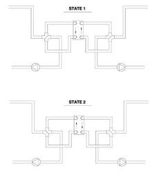
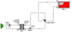
a pair of Tekmar 722 1.25 inch 4 way valves to use to swap directions of flow on both sides of the plate HX, so as to be able to attain and keep maximum efficiency of heat transfer across the plate HX

and

both hot and cold to/from the tank to the plate HX will come out of the _bottom_ of the tank, so as to maintain maximum feasible gravity head across the "open" circulator in hopes of minimizing risk of cavitation as the tank gets to max temps

in a perfect world, where I was far further ahead on my install, I'd enjoy figuring out all the nuances of the plumbing diagrams for maintaining counterflow across both sides of the plate HX, under all scenarios, all on my own-

but- between the schedule of the day job, weather patterns, and other things I need to move on with with the install- I am WAY behind where I'd hoped and aimed to be, so,

PLEASE- someone/ everyone give me some hints/diagrams on the plumbing and valving configurations with the 4-ways to maintain counterflow both when the boiler is the heat source and the tank is the heat sink, and when the boiler'sfire is out and the tank is the heat source and the house is the heat sink. [recall that the boiler, tank, and house are all in a loop on aprimary secondary arrangement, and that the use of the Taco twin tees makes all secondary circuits happily bi-directional, unlike normal "closely spaced tees")

Thanks!!!
 
This one hurts my head, and I don't have my drawing package fired up, but here goes:

Circ is connected to opposite ports of valve (two that never connect to each other). Other two ports are connected to return manifold and hx. Other port of hx is connected to supply manifold.

Same setup for tank circ and its valve, except replace supply/return with top and bottom of coil.

Hope that helps.
 
Thanks NoFo-

any others care to step into my quagmire?

thanks!
 
Still don't have my graphics available, but let me try a few more words:

A 4-way valve has two inlets - call them IN1 and IN2. It also has two outlets - call them OUT1 and OUT2. There's no directionality - flow can go either way. It's just easier to think about as inlet/outlet for me at least.

In one position (straight), IN1 is connected to OUT1 and IN2 is connected to OUT2.

In the other position (reversed), IN1 is connected to OUT2 and IN2 is connected to OUT1.

Connect a circulator to IN1 and IN2, with the inlet connected to IN1.
Connect OUT1 to the return (cold) line to the boiler.
Connect OUT2 to the boiler side of your HX.
Connect the other boiler side HX port to the supply (hot) line to the boiler.

Connection with valve in straight-through position is: Boiler cold inlet - [OUT1...IN1] - circulator> - [IN2...OUT2] - hx - boiler hot outlet

Connection with valve in reversed position is: Boiler cold inlet - [OUT1...IN2] - <circulator - [IN1...OUT2] - hx - boiler hot outlet
 
nofossil said:
Still don't have my graphics available, but let me try a few more words:

A 4-way valve has two inlets - call them IN1 and IN2. It also has two outlets - call them OUT1 and OUT2. There's no directionality - flow can go either way. It's just easier to think about as inlet/outlet for me at least.

In one position (straight), IN1 is connected to OUT1 and IN2 is connected to OUT2.

In the other position (reversed), IN1 is connected to OUT2 and IN2 is connected to OUT1.

Connect a circulator to IN1 and IN2, with the inlet connected to IN1.
Connect OUT1 to the return (cold) line to the boiler.
Connect OUT2 to the boiler side of your HX.
Connect the other boiler side HX port to the supply (hot) line to the boiler.

Connection with valve in straight-through position is: Boiler cold inlet - [OUT1...IN1] - circulator> - [IN2...OUT2] - hx - boiler hot outlet

Connection with valve in reversed position is: Boiler cold inlet - [OUT1...IN2] - <circulator - [IN1...OUT2] - hx - boiler hot outlet

thanks NoFo- I think I'll try to sit down with one of the valves and your description in front of me, and then hopefully it'll start to become clear. I usually enjoy working through puzzles like this myself the hard way, but right now, I need to maximize progress! Winter's coming... !

thanks again

diagrams greatly welcomed, too, if anyone has capability and can throw one together and put it here
 
How about this?
On Edit: Based on "in hot water's" response to your other recent post about flat plates I have the plumbing messed up on the exchanger. The flow reversal part will work though.
 

Attachments

  • flow reversal through fphx001.jpg
    flow reversal through fphx001.jpg
    33.5 KB · Views: 315
Since you are using twin tee's I think you only need one 4 way valve.
Side A twin tee out-pump-heat-exchanger-twin tee in.
Side B (position 1)bottom tank--4 way--pump--heat exchanger--4 way--top of tank
In position 2 ==top tank--4 way--pump--heat ex--4 way--bottom tank.

In other words don't reverse flow in heat exchanger just swap top and bottom tank pipes, and with twin tee's no need to reverse side A.
I will try and draw it out later if this does not make sense.
 
Thanks guys-- I've got to go to a conference for a couple of days, but printed this and will be sneaking peeks during breaks (and checking Hearth now and then during longer breaks).

the depth of knowledge and willingness to help 'round here is just great!
 
kabbott said:
Since you are using twin tee's I think you only need one 4 way valve.
Side A twin tee out-pump-heat-exchanger-twin tee in.
Side B (position 1)bottom tank--4 way--pump--heat exchanger--4 way--top of tank
In position 2 ==top tank--4 way--pump--heat ex--4 way--bottom tank.

In other words don't reverse flow in heat exchanger just swap top and bottom tank pipes, and with twin tee's no need to reverse side A.
I will try and draw it out later if this does not make sense.

way back, I was thinking that as you said, I would not need to swap the flow in the pressurized side, on account of the way that the twin tees don't care about direction of flow in/out where they tie into the primary.

but then I realized that, if I am reversing the flow in the "tank side" of the Plate HX, then, to maintain counterflow, I need to also reverse it in the "boiler side"

Don't I?

I'll be glad to be persuded that I might be able to keep things simpler and do a return/ refund on one of the not too cheap 4 way valves, but I am currently missing how I could maintain counterflow without the pair of valves

thanks, again, all, for the (as usual) excellent input and phenomenal willingness to help
 
On the pressurized side, just do the old two-pumps-pointing-in-different-directions trick. See, for me, that would not work becuase I have a standard Primary Secondary system where one pipe is in front of the other. But with twin-tees, you can reverse flow by just shutting off one pump and turning on another. Then save the 4way for the tank side of things.
 
Here is a diagram. Both pumps always pump same direction, 4 way just selects which pipe (top or bottom of tank) is connected to pump inlet
Always have counter flow through heat exchanger.
 

Attachments

  • untitled.JPG
    untitled.JPG
    16.6 KB · Views: 230
Status
Not open for further replies.