Austroflamm wiring

  • Active since 1995, Hearth.com is THE place on the internet for free information and advice about wood stoves, pellet stoves and other energy saving equipment.

    We strive to provide opinions, articles, discussions and history related to Hearth Products and in a more general sense, energy issues.

    We promote the EFFICIENT, RESPONSIBLE, CLEAN and SAFE use of all fuels, whether renewable or fossil.
Status
Not open for further replies.

Mark_ms

Feeling the Heat
Jan 28, 2008
352
Upstate NY on VT Border
I have cleaned my stove (insert) installed new bushings and Low limit switch, making note of wiring connections. Started stove up, auger came on, but no combustion fan, switched low limit connection around thinking this may be the problem (power unplugged), restarted, auger comes on but no combustion fan.
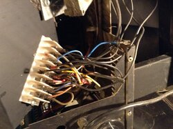
Pull stove out rechecking connections at terminal block, making sure connections are tight and nothing is pinched and I find a Blue and black wire (married) and not connected to terminal block, checking wiring diagram I do not see where this may connect and/or what they go to. there is only one spot on the top side of terminal block where it might go.
I do not have an ignitor nor thermostat.
Right side of diagram would be top of terminal block (I think)
Suggestions???
wiring diagram.JPG
 
Austroflamme uses a capcitor start motor. Make sure the capacitor is wired in and/or good
Ok what does it look like? would I have to pull the motor out to find it?? What about the Wire(s) I found that were not connected??
 
Ok what does it look like? would I have to pull the motor out to find it?? What about the Wire(s) I found that were not connected??

Was that one wire or two because if it was a black wire and a blue wire it could be your combustion blower wires and if they aren't hooked up the combustion blower no come on.

Third terminal location on the right hand side above blue wire to combustion blower and the seventh location same side black wire to the combustion blower.

smokey the 3rd and 7th terminals are as you say.
The two wires I am referring to, the Blue wire comes from the capicitor the Black wire comes from the combustion motor they are joined together with a Spade (female) type of fitting

Capacitor.JPG
Like the first (left) one of the four above.

Looking at the terminal block on the top, most sections have only one available male fitting except where convection fan (black #5) and white #6 is. On the bottom extra fitting is on red (directly beneath white) which I assume white is ground and red is power.
How would I check to see if the capictor is good, I do have a meter but not very familier with it.
Thanx
 
smokey the 3rd and 7th terminals are as you say.
The two wires I am referring to, the Blue wire comes from the capicitor the Black wire comes from the combustion motor they are joined together with a Spade (female) type of fitting

View attachment 78257
Like the first (left) one of the four above.

Looking at the terminal block on the top, most sections have only one available male fitting except where convection fan (black #5) and white #6 is. On the bottom extra fitting is on red (directly beneath white) which I assume white is ground and red is power.
How would I check to see if the capictor is good, I do have a meter but not very familier with it.
Thanx

You likely do not have a meter that reads capacitance.

The stove is wired correctly at the terminal block the way it is. The blue and black wires should go from the terminal block to the wiring that includes the capacitor.

The usual method to rule out the capacitor would be to try a known good one in its place.
I guess what I am trying to say is the blue (capacitor) and black (comb motor) wires that are tied together with spade fitting are not connected to terminal block in any way, I was really wondering where they go...sorry for the confusion
 
I am having trouble finding the manuals online.

ETA: Where do the two wires that come from the terminal block slots #3 and #7 right side go and please be sure there is no power to the stove when you go poking around.

They have to go somewhere and they have to go to that wiring that includes the capacitor..
 
Take a look at page 36 that bar in the middle is the terminal block with the right hand side at the top and going from post 1 to 11 left to right follow the wire off of post 7 it goes to the capacitor and combustion blower motor.
 
Sorry for the delay in getting back to you I work 3rd and I needed to get some sleep.
Please disregard earlier info what follows is more accurate.

Anyway, The terminal block has 8 sections, some have one male connection some 2 and one has three one on top of another (5th section) so I count left to right and then top to bottom
3rd section is blue (combustion)
5 term.is empty
6 term. is convection (black)
7 term is auger (Black)
8 is empty
9 is white
10/11 are brown connected to each other.
5,6 and 7 are in one section (sect. 5)
The only wires I remember disconnecting were for convection fan (2 and 6 black/black)
I am thinking that the blue/black (capacitor/combustion motor) that I found with female connector goes to 5
 
I do acknowledge that the record should reflect that you did in fact say that....:) and were indeed correct in your evaluation
 
I do acknowledge that the record should reflect that you did in fact say that....:) and were indeed correct in your evaluation
Im not seeing where anyone answered your question on this. I am having the same issue. how can these wires be unplugged and not shown on the diagram? if you have your problem fixed can you send me a photo of your wiring please?
 
Im not seeing where anyone answered your question on this. I am having the same issue. how can these wires be unplugged and not shown on the diagram? if you have your problem fixed can you send me a photo of your wiring please?
Did you see where he thanked smokey?He had wires unplugged off connector panel.Use link above for manual.Stove is very simple and has very few wires.
 
Did you see where he thanked smokey?He had wires unplugged off connector panel.Use link above for manual.Stove is very simple and has very few wires.
Yes sir. I did see that a thank you was given. I simply cannot understand where the wires actually go. Nowhere on the schematic is a blue/black capacitor wire nor a double brown capacitor wire ever mentioned. I will attempt to attach an image of mine. I totally agree that this should be easy, however I just don't want to burn anything up. Thank you for your prompt response,and any help from you will be greatly appreciated.
 

Attachments

  • image.jpg
    image.jpg
    237.2 KB · Views: 1,419
Yes sir. I did see that a thank you was given. I simply cannot understand where the wires actually go. Nowhere on the schematic is a blue/black capacitor wire nor a double brown capacitor wire ever mentioned. I will attempt to attach an image of mine. I totally agree that this should be easy, however I just don't want to burn anything up. Thank you for your prompt response,and any help from you will be greatly appreciated.
The cap. is hardwired to the motor,so there is no need to show it,it comes as a unit.Go by the motor wires.
 
The cap. is hardwired to the motor,so there is no need to show it,it comes as a unit.Go by the motor wires.
Gotcha, I just can't hardly believe that they would have two wires butted together coming from or going to the capacitor with an uninsuated female spade plug, just dangling around. If you look at the image I inserted into my last comment you will see the wires just hanging out unattached. Seems strange. Thank you for your fast response.
 
Did not look at picture before.There should be no unplugged wires on an integra.Also on the connector board there are some spots that have an adapter and 2 wires in one spot.Unless you have an pre 1992 old style,they were different,as not all got upgraded.
 
By the way the brown wires/looks like connector/should be sealed,is only a splice.And the cap is shown in the main wiring diagram.So how many wires do you have left unplugged and where do they go?Lets get you up and running.
 
I don't see the brown wire in pic, but that may just be me, I see the blue that is disconnected I'm thinking it may be the blue/brown disconnected may be for thermostat circuit?
 
I don't see the brown wire in pic, but that may just be me, I see the blue that is disconnected I'm thinking it may be the blue/brown disconnected may be for thermostat circuit?
If you blow picture up you will see the 2 side spliced brown wires covered in shrink tubing,yours has same.Is for cap.
 
Status
Not open for further replies.