I redesigned the control system for my Tarm and am sharing it for those who might find it useful or to provide ideas for design of other control systems. In my system the Tarm feeds only storage, and the balance of the heating system (future radiant floor) will be provided with heat from storage. Right now my inside installed storage tank provides all the heat I need by serving as a large radiator.
My Tarm came with basic internal controls: an operating thermostat to turn "off" the draft fan at a user set maximum water temperature (180-190F) and turn the draft fan back "on" as temperature drops, a lo-limit control to shut the Tarm down at end of burn, and an overheat thermostat to shut the Tarm down at 210F. The Tarm also has terminals to tie into the lo-limit circuit.
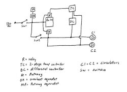
1) SW1 is the master switch to the system.
2) SW2 allows the exercise of C1 and C2 at any time, but especially when the boiler is shut down. I exercise C1 and C2 about every 2 weeks during the off-season.
3) M (Automag) activates on power loss to provide overheat protection via a gravity fed loop. I also installed AM (Automag aquastat - NC) set at 210F in series with the Automag circuit. It is a strap-on type and is mounted on the boiler supply pipe. If boiler supply reaches 210F, the AM contacts open and M loses power and activates to feed the gravity loop in the event of a power-on overheat.
4) OH (overheat aquastat - NO) has a sensor in a boiler well and is set at 210F. If the boiler reaches 210F, the OH contacts close and feed power to C1 and C2 to draw excess heat from the boiler if a power on overheat. This is a fail-safe control, in the event the electronic controls fail to provide power to C1 and C2 in a power on overheat situation.
5) I installed R (Relay), 120AC coil, inside the Tarm, with the coil powered by the Tarm lo-limit circuit. The Relay contacts (120AC) are powered independently of the Tarm circuitry, just to make sure I didn't overload the internal Tarm circuit. When the Tarm is turned on, the Relay contacts close, and power is delivered to the Temperature Controller, which also provides power to the the Differential Controller and C1 and C2. When the Tarm lo-limit shuts the Tarm down, the Relay contacts open and power to the Temperture Controller, Differential Controller, C1 and C2 all are shut down.
6) TC (Temperature Controller - 2 stage) is turned on when the Tarm is turned on. It has a single sensor mounted on the boiler supply pipe. Stage 1 is activated and DC (Differential Controller) is turned on when hot water from the boiler rising by gravity reaches 165F. The differential is 5F, and DC (Differential Controller) is turned off when hot water from the boiler falls to 160F. (I also have the Termovar for the Tarm to provide boiler return water protection at 150-160F.)
7) DC (Differential Controller) has sensors on the boiler supply pipe and the storage return pipe. DC turns C1 on when boiler supply is 16F higher than storage return, with an 8F differential. This assures that C1 operates only when effective heat can be delivered to storage. These are fixed on my DC; other differential controllers allows adjustment of these values.
8) TC (Temerature Controller) Stage 2 is activated and C2 is turned on when hot water from the boiler reaches 188F. The differential is 3F, and C2 is turned off when hot water from the boiler falls to 185F. C2 also feeds storage. C1 and C2 are in series, and gpm flow increases 4-6 gpm when C2 is turned on. The reason for C2 is to increase flow and draw off excess btu's as boiler temperature approaches maximum, and to minimize boiler idling at high storage return temperatures.
The components:
Automag (M) - bought new with the Tarm
Strap-on aquastat for use with Automag (AM) - bought new on ebay
L4008B overheat aquastat (OH) - bought new with the Tarm
Relay (R) - any 120VAC coil relay with contacts rated for desired load(s) - bought at an electronics surplus store
TC - Honeywell T775A1019 Electronic Temperature Controller - bought used on ebay
DC - Steca TR0301U differential controller - bought new on ebay
C1 - Grundfos 15-58 - bought new on ebay
C2 - Taco 007 - bought new on ebay
SW1 and SW2 - home lighting toggle switches
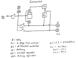
Edit -- Oops! When I did the diagram I tried to further simplify the control wiring I actually installed, and the result being that the wiring diagram is in error in that C1 and C2 will always be "on" at the same time, rather than separately controlled. I will post a corrected diagram shortly.
My Tarm came with basic internal controls: an operating thermostat to turn "off" the draft fan at a user set maximum water temperature (180-190F) and turn the draft fan back "on" as temperature drops, a lo-limit control to shut the Tarm down at end of burn, and an overheat thermostat to shut the Tarm down at 210F. The Tarm also has terminals to tie into the lo-limit circuit.
1) SW1 is the master switch to the system.
2) SW2 allows the exercise of C1 and C2 at any time, but especially when the boiler is shut down. I exercise C1 and C2 about every 2 weeks during the off-season.
3) M (Automag) activates on power loss to provide overheat protection via a gravity fed loop. I also installed AM (Automag aquastat - NC) set at 210F in series with the Automag circuit. It is a strap-on type and is mounted on the boiler supply pipe. If boiler supply reaches 210F, the AM contacts open and M loses power and activates to feed the gravity loop in the event of a power-on overheat.
4) OH (overheat aquastat - NO) has a sensor in a boiler well and is set at 210F. If the boiler reaches 210F, the OH contacts close and feed power to C1 and C2 to draw excess heat from the boiler if a power on overheat. This is a fail-safe control, in the event the electronic controls fail to provide power to C1 and C2 in a power on overheat situation.
5) I installed R (Relay), 120AC coil, inside the Tarm, with the coil powered by the Tarm lo-limit circuit. The Relay contacts (120AC) are powered independently of the Tarm circuitry, just to make sure I didn't overload the internal Tarm circuit. When the Tarm is turned on, the Relay contacts close, and power is delivered to the Temperature Controller, which also provides power to the the Differential Controller and C1 and C2. When the Tarm lo-limit shuts the Tarm down, the Relay contacts open and power to the Temperture Controller, Differential Controller, C1 and C2 all are shut down.
6) TC (Temperature Controller - 2 stage) is turned on when the Tarm is turned on. It has a single sensor mounted on the boiler supply pipe. Stage 1 is activated and DC (Differential Controller) is turned on when hot water from the boiler rising by gravity reaches 165F. The differential is 5F, and DC (Differential Controller) is turned off when hot water from the boiler falls to 160F. (I also have the Termovar for the Tarm to provide boiler return water protection at 150-160F.)
7) DC (Differential Controller) has sensors on the boiler supply pipe and the storage return pipe. DC turns C1 on when boiler supply is 16F higher than storage return, with an 8F differential. This assures that C1 operates only when effective heat can be delivered to storage. These are fixed on my DC; other differential controllers allows adjustment of these values.
8) TC (Temerature Controller) Stage 2 is activated and C2 is turned on when hot water from the boiler reaches 188F. The differential is 3F, and C2 is turned off when hot water from the boiler falls to 185F. C2 also feeds storage. C1 and C2 are in series, and gpm flow increases 4-6 gpm when C2 is turned on. The reason for C2 is to increase flow and draw off excess btu's as boiler temperature approaches maximum, and to minimize boiler idling at high storage return temperatures.
The components:
Automag (M) - bought new with the Tarm
Strap-on aquastat for use with Automag (AM) - bought new on ebay
L4008B overheat aquastat (OH) - bought new with the Tarm
Relay (R) - any 120VAC coil relay with contacts rated for desired load(s) - bought at an electronics surplus store
TC - Honeywell T775A1019 Electronic Temperature Controller - bought used on ebay
DC - Steca TR0301U differential controller - bought new on ebay
C1 - Grundfos 15-58 - bought new on ebay
C2 - Taco 007 - bought new on ebay
SW1 and SW2 - home lighting toggle switches
Edit -- Oops! When I did the diagram I tried to further simplify the control wiring I actually installed, and the result being that the wiring diagram is in error in that C1 and C2 will always be "on" at the same time, rather than separately controlled. I will post a corrected diagram shortly.