Boiler loop pump location

  • Active since 1995, Hearth.com is THE place on the internet for free information and advice about wood stoves, pellet stoves and other energy saving equipment.

    We strive to provide opinions, articles, discussions and history related to Hearth Products and in a more general sense, energy issues.

    We promote the EFFICIENT, RESPONSIBLE, CLEAN and SAFE use of all fuels, whether renewable or fossil.
Status
Not open for further replies.

NCFord

Member
Jun 5, 2011
203
central NC
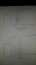
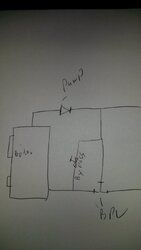
I am getting ready to hook up my storage tanks and need to fix some of my plumbing first. I screwed up the boiler pump location as seen in the top diagram. (it's currently works right now without storage because I took out the cartrage) So I need to move the pump to either like the second diagram or place the pump between the BPV and return on the boiler. It seems to me most times it's located near the return, but I would like to locate it on the top because it would be a much much easier plumbing job involving very little time and
effort. Is there any advantage or disadvantage to either?
 

Attachments

  • boiler pic.jpg
    boiler pic.jpg
    72.7 KB · Views: 194
Neither location, I believe most return protection valves want the circulator between the return protection valve and the inlet (return) of the boiler.

TS
 
Like BoilerMan says.
Between the return protection valve and the inlet (return) of the boiler is the "preferred" way.
 
Last edited:
  • Like
Reactions: BoilerMan
That's what I was afraid of, it's no big deal just a bit more disassembly and more time involved.
I still don't understand why having the pump located between boiler supply and the tee going to the
BPV would not work. It would put pressure to the valve and to storage(by pushing) the same way having it located on the return side pulls water through both.
 
Well, I took a second look at your schematic, and I guess you can also put your circulator on the supply side of the wood boiler
Your bottom schematic.
The circulator will see just hotter water, the water flows are still the same as in the "preferred" schematic.
 
Thanks for the help, I can finally get my storage up and running. Everything is in place for the switch over except for changing this pump location. I really wish I had not had a brain fart when I first plumbed it over the summer. I have time early this week to get this done but don't know if I want to take the boiler off line with all this cold weather. Oh well!
 
Don't forget the bypass valve, so you can dial in your best setting ! ! !
I don't see this valve in your schematics
 
passionforfire,
I would really like to place it on the top because it really would be a lot easier, but I don't want to do something
that won't work.
 
I don't have a bypass valve. Is that what is on your diagram on the vertical section?
 
What is the brand and model of the BRWTP valve ?
Boiler Return Water Temperature Protection Valve
 
I don't have a bypass valve. Is that what is on your diagram on the vertical section?

yes

Some of these valves don't close 100%, and then there is always some flow trough it.
This can slow down how fast your storage tank will be charged.
The water will look for the easiest way.
You can dial this in with that valve
 
Last edited:
OK, I am new at all this, I have read about people using a by-pass valve but don't know exactly why? Also,
does it simply by-pass the BPV with a manual valve? Like the pic I drew? Caleffi BPV
 

Attachments

  • boilerpic2.jpg
    boilerpic2.jpg
    72 KB · Views: 151
I just looked up the caleffi, it's a 280 series.
 
Not like in your last schematic.
That is parallel.
This would bypass the Caleffi 280 ThermoMix completely. That's not the intent.

You can forget about this valve if you use the Caleffi 280 ThermoMix !
See
http://www.caleffi.us/en_US/caleffi/Details/News/files/Caleffi_280_ThermoMix.pdf

The 280 closes completely at 18F temp differential

When the mixed flow to the boiler temperature Tmix is greater than the set point of the boiler protection mixing valve by approximately 18°F (10°C), the bypass flow from the boiler port closes and water returns to the boiler at the same temperature as the return flow from the system.
 
  • Like
Reactions: ewdudley
OK, I am new at all this, I have read about people using a by-pass valve but don't know exactly why? Also,
does it simply by-pass the BPV with a manual valve? Like the pic I drew? Caleffi BPV

Some return protection mixing valves need a 'balancing valve' in the bypass leg (not parallel to the bypass leg as shown in your drawing above). If the Caleffi documentation doesn't require one then you're probably OK without one unless the loop to storage is long or high resistance.

The pump can go either on the bottom between the mixing valve and the boiler, or on the top between the boiler and the bypass tee. The pump will be hotter on top, but modern pumps don't care, at least according to their spec sheets. Ideally for air separation the pump would be on top and the air separator would be between the boiler and the pump.
 
What is the cost of the 280 ?
I'm curious of this also, I've had nothing but total success with any Caleffi component I've used. And No I'm not involved in any way with Caleffi or the sale of anything for that matter. I just like them.

TS
 
I do have the 280 so I won't worry about the bypass. I can't remember what the cost was.
 
I know what you mean, I seem to learn more here than I can keep up with. So after all this it seems I can place the pump on the
top between boiler supply and the bypass tee. Thanks! I can't wait for storage its been a huge work in progress for the last 2 months.
 
Not like in your last schematic.
That is parallel.
This would bypass the Caleffi 280 ThermoMix completely. That's not the intent.

You can forget about this valve if you use the Caleffi 280 ThermoMix !
See
http://www.caleffi.us/en_US/caleffi/Details/News/files/Caleffi_280_ThermoMix.pdf

The 280 closes completely at 18F temp differential

When the mixed flow to the boiler temperature Tmix is greater than the set point of the boiler protection mixing valve by approximately 18°F (10°C), the bypass flow from the boiler port closes and water returns to the boiler at the same temperature as the return flow from the system.


The pump could be installed on the supply pipe from the boiler, and the valve will operate properly.

With the Caleffi 280 there is no need to have a balance valve in the bypass line it is a 100% shutoff valve. The pump is shown on the cooler return water to allow the pump to operate in lower water temperatures.

Solid fueled boilers subjected to long power outages can sometimes experience excessive temperatures. Most hydronic pumps are rated to 225F max operating temperatures.

You may want to put a ball valve in the bypass so you could quickly isolate the valve for service or cleaning. I like to surround all serviceable devices with isolation valves. No need to draindown the system or introduce air if you can isolate close to the component, pumps, mixers, etc.


Install a good air purger at the boiler supply from the top of the boiler. Best air removal is at the hottest point in the piping. The expansion tank should connect there also. It does not need to be mounted there, it could be mounted across the room, but the piping connection needs to be upstream of the pump for best operation.

A drain and purge valve down low is helpful, as well as one on the bottom of the boiler.
 

Attachments

  • Screen shot 2014-01-04 at 2.25.37 PM.png
    Screen shot 2014-01-04 at 2.25.37 PM.png
    71.6 KB · Views: 192
Thanks Rob for the advice, all the stuff you mentioned is already in place
 
Status
Not open for further replies.