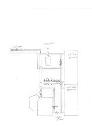
I am installing a Harmon PB-105 pellet boiler with 240 gallons of buffer storage. I am a contractor, but not a heating specialist. I have a little knowledge,but I could use some guidance. My goals are to heat from the buffer tanks when possible. Then charge the tanks from the boiler. Finally, heat from the boiler when demand is too great for the tanks.My heat loss calcs are 39000Btu. Boiler output 113900Btu. 240 gallons of water should yeild 79000Btu's @ 40degree delta [180 to 140]. That should give me 2 hours of heat even on the coldest day of the year. I have attached a drawing for reference. It is to scale, so it literally represents what I would be piping. My questions are:
1.Does this look right in general?
2.If you look closely there are two primary circuits running clockwise[boiler], and counter clockwise[buffers]. A third would be the boiler charging the tanks running clockwise.
Will the pull of the circs create the flow as I suspect?
3. I want to use one of the new adjusting pumps such as a grundfos alpha, is it necessary or even wise to use them in all three positions?
4. In the drawing I have a mixing valve at the boiler return. In retrospect I believe a diverter valve at the T above the #3 pump is a better location.
5.Should the boiler pump could be relocated to the return side of the boiler?
Thanks for any help. I am open to direction on this project. I do have a wife and daughter that will be asking for heat soon, so time is of the essence. I also need help with incidentals, such as piping diameter, purge valves, air eliminators, ect.