Can Anyone Recommend Piping Diagram and Floor Layout Tools?

  • Active since 1995, Hearth.com is THE place on the internet for free information and advice about wood stoves, pellet stoves and other energy saving equipment.

    We strive to provide opinions, articles, discussions and history related to Hearth Products and in a more general sense, energy issues.

    We promote the EFFICIENT, RESPONSIBLE, CLEAN and SAFE use of all fuels, whether renewable or fossil.
Status
Not open for further replies.

velvetfoot

Minister of Fire
Dec 5, 2005
10,202
Sand Lake, NY
I know it's been talked about before, but if you can recommend anything off the top of your head, could you please? Thanks.
 
Google it. lots of free software out there.
 
Microsoft Visio is pretty good for piping diagrams. Floor layout I would consider sketchup.
 
  • Like
Reactions: velvetfoot
Google can be great resource to find free or inexpensive design tools. Perhaps someone has some suggested search terms or has tried a couple of such tools and found one worked well?
 
The Taco one worked well for me
 
I've been messing with it for a while. Unless I'm missing something, I couldn't add an indirect tank, and used a mixing tank instead. It said to buy the Professional version to add an indirect tank. That version is $1800. It's cool that it does calculations and all, but I my current impression is that it's somewhat inflexible, and that it might be hard to make it look like what you want it to, even neglecting the calculations aspect.

edit: Still messing. Found hydronic heat exchanger object as an analogue to Froling Energy Tank. The program is quite cool, but I'll still with what I said before.

edit: Found the indirect water heater under terminal units. I think I'll keep quiet for now.
 
Last edited:
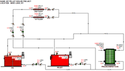
Just for giggles here's what I have so far. There's stuff missing for sure that I know about like t&p relief valves, expansion tanks(s), auto fill, tempering valve, pipe lengths,etc. What I'm not sure about are check valves-maybe I'll put a thread up on that. What's interesting is that you can put the loads on it and it'll calculate pump flows, head loss, and boiler requirements. The numbers are big because of the Froling Energy Tank modeling (yeah, that's what I call it :) ), which recommended a 4 gpm flow through the transfer coil and I figured going from 50F well water (not sure) to 120F supply requiring 138,000 btu/hr.

I still have to figure out how to incorporate the buffer (heat exchanger) in the "model". It has a lot of potential and is helping me to visualize hydronic relationships.

test schematic.png
 
Status
Not open for further replies.