Check valves and flow restriction?

  • Active since 1995, Hearth.com is THE place on the internet for free information and advice about wood stoves, pellet stoves and other energy saving equipment.

    We strive to provide opinions, articles, discussions and history related to Hearth Products and in a more general sense, energy issues.

    We promote the EFFICIENT, RESPONSIBLE, CLEAN and SAFE use of all fuels, whether renewable or fossil.
Status
Not open for further replies.

goosegunner

Minister of Fire
Oct 15, 2009
1,469
WI
I posted this the other day about adding a parallel pump in my system.

https://www.hearth.com/talk/threads/parallel-pump-to-reduce-idle.86883/


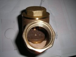
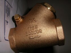
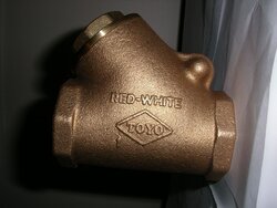
After looking it over more it would be much easier to add the pump in the boiler return. To do so I will need a flow check in the 1-1/2" boiler return.

How much restriction do the flow checks cause?

Can anyone suggest a good flow check valve?

If it is excessive I will cut the supply and put the bypass there. The integrated check valves in my grundfos pumps would be sufficient.

gg
 

Attachments

  • IMGP4693.JPG
    IMGP4693.JPG
    107.6 KB · Views: 429
  • imgp4694.jpg
    imgp4694.jpg
    161.3 KB · Views: 348
  • IMGP4695.jpg
    IMGP4695.jpg
    136.4 KB · Views: 314
the main thing to watch with that type of check valve is the flow rate. If you oversize the valve that flapper will bang around inside due to lack of flow velocity to hold it full open.

You need to know the flow rate you will be moving thru the valve and size it to that.

Often times the check is a few sizes smaller than the pipe size. it's the Cv number that holds the clue. if you plan on flowing 6 gpm, a valve with a cv of 6 would work. a large valve like that with small flow, that is a good valve for a sump pump, plenty of flow to hold it wide open.

For hydronics look for a spring check and one with a soft seat. That type of valve would have a cone shaped valve mechanism and have better flow charastrics and seal tighter with a little help from a spring.

Here is an example of a good hydronic spring check. Find these cone shaped, soft seat, spring checks in the pump body, or sometimes built into the isolation valve/ flange. Generally they have a 1/2 psi "pop" so it doesn't require much pump to pop them open. This is from Grundfos 15-58 and can flow 8 gpm or so without a problem, no need to use a big chunk of brass like that.

hr
 

Attachments

  • Screen shot 2012-06-01 at 5.36.07 PM.png
    Screen shot 2012-06-01 at 5.36.07 PM.png
    72.7 KB · Views: 487

Can also be installed in the vertical position as long as the flow is upwards.

**Edited to add the following;

Hrmm this was in reply to hobbyheater's post, tried to quote but didn't work for some reason...
 
I bought one of the brass check valves in 1-1/2" today. Maybe that is not what I need.

I decided to put the bypass in the return for simplicity.

The bypass loop will have a 1 -1/4" copper, a Grundfos 15-58 with a flow check inside.

The Main boiler pump above it is a 26-99 with flow check. It flows,

14gpm on low
18 gpm on med
22 gpm on high

I bought a 1-1/2' brass Check valve to put in the main boiler supply so the bypass line does not short circle if the main boiler pump is not running.

Here is a picture of what I was thinking.

ggBoilerbypasspump.jpg
 
I bought one of the brass check valves in 1-1/2" today. Maybe that is not what I need.

I decided to put the bypass in the return for simplicity.

The bypass loop will have a 1 -1/4" copper, a Grundfos 15-58 with a flow check inside.

The Main boiler pump above it is a 26-99 with flow check. It flows,

14gpm on low
18 gpm on med
22 gpm on high

I bought a 1-1/2' brass Check valve to put in the main boiler supply so the bypass line does not short circle if the main boiler pump is not running.

Here is a picture of what I was thinking.

ggView attachment 67935
Adding a pump there would be another pump in series. If that's what you want, it would be simpler just to put the new pump where the proposed check valve would go and forget the end around piping. The 26-99 would pull through the new pump when it was not running and hardly know it's there. In either case you wouldn't want an IFC in the new pump.
 
Adding a pump there would be another pump in series. If that's what you want, it would be simpler just to put the new pump where the proposed check valve would go and forget the end around piping. The 26-99 would pull through the new pump when it was not running and hardly know it's there. In either case you wouldn't want an IFC in the new pump.

Not really knowing what is right or wrong I thought the 15-58 would restrict the 1-1/2" line.

I guess I thought for the small amount of time that the 15-58 would actually run a by pass would be the thing to do.

The things I want,

1. Control the 15-58 independently of the boiler.

2. Have it start before boiler set point it increase flow to minimize idle near end of storage charge.

3. Use the 15-58 with a battery backup to assist cooling the boiler in a power loss.

Would the 15-58 open the check in the 26-99 if it was not running?

Would series be better than a by pass on the supply?

gg
 
Not really knowing what is right or wrong I thought the 15-58 would restrict the 1-1/2" line.

I guess I thought for the small amount of time that the 15-58 would actually run a by pass would be the thing to do.

The things I want,

1. Control the 15-58 independently of the boiler.

2. Have it start before boiler set point it increase flow to minimize idle near end of storage charge.

3. Use the 15-58 with a battery backup to assist cooling the boiler in a power loss.

Would the 15-58 open the check in the 26-99 if it was not running?

Would series be better than a by pass on the supply?
You're probably right that the 15-58 in series would add substantial resistance, but I was thinking that until storage got hot the 26-99 wouldn't notice much really, and then when the 15-58 kicks in away we go.

But as you suggest, it's unlikely that series would be better in the first place. At 22 gpm you'd have 4 feet per second in 1.5" pipe, going to 33 gpm would only double the head loss. For series pumps you stack the pump curves and for parallel you add one to the right of the other. Since we're over on the right side of the 26-99 curve we can see that if we double the head we get a lot more flow by adding the 15-58 curve to the right instead of stacking it on top.

So parallel would probably be best. You could move the existing pump down to the return side, makes no difference. Just put one pump where the proposed check valve was going to go and put the other in the bypass, with IFCs in both pumps. You might want to bypass the Danfoss with the extra pump, but the Danfoss has a nice big Cv so it might not be worth the extra plumbing effort.

And perhaps leave the option in your control wiring of having the 15-58 be your main pump and reserve the 26-99 for high flow mode. With as low as 30 degF of deltaT to work with the 15-58 would be plenty of pump virtually all the time.


Both on the return side is an option I had not considered. I seems most guys like the pump on the return side. When I set it up initially I put it on the supply because the Tech support for Danfoss said it would help air removal.

My first thought was to put the bypass on the supply side. My fear with the supply side is getting the the movement in the piping to get the new stuff in. I have sweat flanges so removing them might be tuff without damaging them. I need to look this over some more. Maybe its time to drop the main pump to the return side.

Would you leave the air removal in place and just move the pump to the return side?

Here is a picture of my initial plan.

boilerboosterpump.jpg
 
Both on the return side is an option I had not considered. I seems most guys like the pump on the return side. When I set it up initially I put it on the supply because the Tech support for Danfoss said it would help air removal.

My first thought was to put the bypass on the supply side. My fear with the supply side is getting the the movement in the piping to get the new stuff in. I have sweat flanges so removing them might be tuff without damaging them. I need to look this over some more. Maybe its time to drop the main pump to the return side.

Would you leave the air removal in place and just move the pump to the return side?
For best air removal your current set up is done right. For me personally I can't get too worked up about air removal in a boiler loop that's headed straight over to storage, and where pockets of air elsewhere in the system can be easily located and bled off permanently.

But since you've come this far to get it right I'd say take the bull by the horns and do whatever it takes to maintain the integrity of a superior design.

I'm no sweat plumber, but my instinct would be to sawzall a piece out of the section to the left of the air eliminator, move the eliminator to the left, tee down and elbow over to the extra pump, and then tee back in on the vertical leg that goes down to the Danfoss. If you work it right it looks like the only unsweating you'd have to do would be just the one joint on the right side of the air eliminator itself, and not even that if you sawzall into the piece between the eliminator and the existing pump. (Or even use the right tool like they do on 'This Old Checkbook'.)

Then both pumps would be downstream of the air eliminator and they both would be pretty much identical from a hydraulic schematic point of view.
 
For best air removal your current set up is done right. For me personally I can't get too worked up about air removal in a boiler loop that's headed straight over to storage, and where pockets of air elsewhere in the system can be easily located and bled off permanently.

But since you've come this far to get it right I'd say take the bull by the horns and do whatever it takes to maintain the integrity of a superior design.

I'm no sweat plumber, but my instinct would be to sawzall a piece out of the section to the left of the air eliminator, move the eliminator to the left, tee down and elbow over to the extra pump, and then tee back in on the vertical leg that goes down to the Danfoss. If you work it right it looks like the only unsweating you'd have to do would be just the one joint on the right side of the air eliminator itself, and not even that if you sawzall into the piece between the eliminator and the existing pump. (Or even use the right tool like they do on 'This Old Checkbook'.)


Then both pumps would be downstream of the air eliminator and they both would be pretty much identical from a hydraulic schematic point of view.

Ok I think I understand this,

Fortunately the air eliminator has threaded connectors so I should be able to move that left easy enough.

As far as Putting the T back in point in the Danfoss leg, will the flow just balance itself, back into the main supply line?

Would benefit any to try and put the T after the main pump and before the Danfoss leg?

Thanks for all your time and assistance

gg


gg
 
Would benefit any to try and put the T after the main pump and before the Danfoss leg?

As far as Putting the T back in point in the Danfoss leg, will the flow just balance itself, back into the main supply line?
Flow will work out the same, give or take the difference in pressure drop between using one path or the other, which I would guess would be on the order of fifty thousandths of a psi.
 
Thanks for your help on this!

I believe I have a plan,

We will first remove pump and piece from right side of air separator.

Move air separator to left, add T for bypass to right.

Try and break the joint between the boiler supply and Danfoss T.

If that fails cut and leave a stubb on pump flange piece.

Cut out Danfoss T and replumb.

I am wondering with this new set up if I could run with two 15-58's?

The second would come on and off as needed and it would be cheaper to run and replace instead of the 26-99.
gg
 
I have been following this site for about a year now as I am installing an Econoburn EBW 200 just like the one goosegunner shows above.
If I could, I would like to restart this thread as I have some of the same questions gg had on his pump issue.
GG-on your original install did you use just the one pump on the supply side or is there another behind the boiler? Econoburn recommends their two pump on/off system but I like just one on the return side. I use a Caleffi 280 boiler protection valve on the bottom of the bypass.
I was also planning on putting a bypass around my main pump, on the return side, that would have another pump on it. Both pumps are Grundfos 15-58. My ideas was that the bypass pump would be wired to the overtemp circuit on the boiler so that it would come on in an overtemp situation, instead of installing a gravity dump above the boiler. Would these two pumps running in parallel provide enough increased flow over just the main pump running to cool the boiler back down? All my piping from boiler to storage is 1 1/4".
After reading gg thread I see that this pump might also serve as a way to increase flow near the high point of the burn.
My runs are not long like gg's on my install. Can anyone also comment on how far I should have my tees, for the bypass, away from the main pump?
Thanks a bunch.
Boardroom.
 
When I installed my system, Econoburn informed me that their instructions for using the two pumps would not be the best when using storage. The way the control works, a boiler protection valve works best when having large volume of cool return water like heating the tank for the first time of the season.

gg
 
Thanks gg. That's one mystery solved already.
I plan to use a battery backup to take care of a power outage. The issue I have now is how to handle an overtemp situation, either from a pump failure or an overtemp during regular burning.
My plan is to put a bypass around my main pump, as gg did in the pictures, and wire it to my overtemp circuit on the boiler. If the main pump fails the boiler will go overtemp and turn this spare circulator on. If it is a regular overtemp during a normal burn cycle, it will also come on, in conjunction with the main pump.
I am not sure if this will work though as I don't understand all the science behind two pumps running in parallel.
p.s. I am using 1000 gallons of pressurized storage.
 
Status
Not open for further replies.