Circulator selection - calculating head loss

  • Active since 1995, Hearth.com is THE place on the internet for free information and advice about wood stoves, pellet stoves and other energy saving equipment.

    We strive to provide opinions, articles, discussions and history related to Hearth Products and in a more general sense, energy issues.

    We promote the EFFICIENT, RESPONSIBLE, CLEAN and SAFE use of all fuels, whether renewable or fossil.
Status
Not open for further replies.

mousebndr

Member
Aug 5, 2011
60
Australia
Hey folks,

Have been playing with the pump size tool at http://www.taco-hvac.com/uploads/FileLibrary/SelectingCirculators.pdf

Everything seems straight forward until we get to head loss.

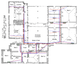
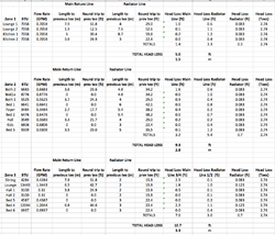
I dont know the pipe length for my 3rd zone as yet, but in my first two zones I used 500ft of AL-PEX total for all pipework, the calculator says I need a flow rate of 14 GPM.

HL = k * c * L * (f ^1.75)
0.0034 * 0.933 * 500 * ( 14 ^1.75 )
=161 ft head

This seems to be off the charts.

Am I including too much pipe?
 
Please show your work for the length of pipe. Perhaps we can spot something.
 
Make sure you divide the flow thru the parallel loops. IE if you have 2 250' loops of 1/2" PAP, you will split the flow thru the loops, and calculate the head thru each loop. they don't get added together. if you have 5 loops 100' long, at 1 gpm each, you get 4.3 ft Hd. if you have 1 loop 500' long, and move 2 gpm thru it, you have 72' head.

as in: if you have a zone that is 3 200' loops of 1/2" pex and each loop gets 1.5 GPM and is fed by 50' of 3/4 pex, you would calculate the head loss of 1.5 gpm thru 200' of 1/2"pex, and get 16' head.

and then you calculate the head loss of 4.5GPM thru the 100' (round trip) 3/4" pex. that gives you 11' head. add them up and you get 27' head. if you want to save some head, use 1" pex, and you only get 3.4 feet head. use a smaller circulator. save some electricity.

divide the system into chunks.

good luck. I built a calculator in excel to do the heavy lifting. you can only do those calcs by hand so many times.

Karl
 
Karl_northwind said:
Make sure you divide the flow thru the parallel loops. IE if you have 2 250' loops of 1/2" PAP, you will split the flow thru the loops, and calculate the head thru each loop. they don't get added together. if you have 5 loops 100' long, at 1 gpm each, you get 4.3 ft Hd. if you have 1 loop 500' long, and move 2 gpm thru it, you have 72' head.

as in: if you have a zone that is 3 200' loops of 1/2" pex and each loop gets 1.5 GPM and is fed by 50' of 3/4 pex, you would calculate the head loss of 1.5 gpm thru 200' of 1/2"pex, and get 16' head.

and then you calculate the head loss of 4.5GPM thru the 100' (round trip) 3/4" pex. that gives you 11' head. add them up and you get 27' head. if you want to save some head, use 1" pex, and you only get 3.4 feet head. use a smaller circulator. save some electricity.

divide the system into chunks.

good luck. I built a calculator in excel to do the heavy lifting. you can only do those calcs by hand so many times.

Karl


I have three zones, with flow rates of
Z1: 2.823
Z2: 5.7289
Z3: 5.4776

Each zone is a 3/4" ALPEX loop with 1/2" ALPEX connections teeing off to each radiator. I want to have a single pump sitting before the manifold.

So... I think your saying that you work out the head of each zone separately. Then select the highest zone as your head loss?
 
Got it. you have the right idea.
I'd look at the pressure drop on each radiator (panel radiators?) and TRV if you're using one, and go from there.
a schematic of course would help.

cheers,
karl
 
Karl_northwind said:
Got it. you have the right idea.
I'd look at the pressure drop on each radiator (panel radiators?) and TRV if you're using one, and go from there.
a schematic of course would help.

cheers,
karl

Well... I thought I understood, but I am still coming out way of the charts.


Zone 1 has 119.4ft of 1/2" and 114.8ft of 3/4". Flow rate of 2.8GPM
Zone 2 has 167.3ft of 1/2" and 120.7ft of 3/4". Flow rate of 5.7GPM
Zone 3 has 211.3ft of 1/2" and 147.6ft of 3/4". Flow rate of 5.4GPM

I am getting heads of 52ft, 224ft and 258ft

There does not seem to be a pump about that can do this. Although Zones 1 and 2 are currently operated as a single loop with a single Grundfos UPS 100.

Have attached a diagram. What am I missing? :)
 

Attachments

  • Hydronic Floorplan V2.png
    Hydronic Floorplan V2.png
    61.8 KB · Views: 832
Do you have diverter or venturi tees or are these all balanced?

I have to assume that since you don'thave the ends of the home runs connected, you'll have to balance the radiators.
if you want a good head loss calc, you'll have to break each individual length. as in: let's take the left run because it's simple. (is that still west in Australia or East?)
if the zone needs 3 GPM, you'll need to calculate out the head loss for 3 gpm for the home run (round trip) to the tee off for the first radiator in the Lounge/dining, and then set that aside. if that radiator needs 1.5 gpm, then you take the head loss for 1.5 GPM in the remaining home run piping out to where the second radiator tees off(round trip) set that aside.
then take the head loss for the 1.5 gpm in the 1/2" pipe going to the radiator and the pressure drop of the radiator itself at 1.5 gpm, and then add all those head losses up.
so if you have 2' head loss in the first calc,
then have3' in the second calc, and then 2' in the third calc,
you'd end up with 7' head loss.

I hope that helps.

anyone else out there is welcome to second guess my method, or offer other suggestions.
karl
 
Karl_northwind said:
Do you have diverter or venturi tees or are these all balanced?

I have to assume that since you don'thave the ends of the home runs connected, you'll have to balance the radiators.
if you want a good head loss calc, you'll have to break each individual length. as in: let's take the left run because it's simple. (is that still west in Australia or East?)
if the zone needs 3 GPM, you'll need to calculate out the head loss for 3 gpm for the home run (round trip) to the tee off for the first radiator in the Lounge/dining, and then set that aside. if that radiator needs 1.5 gpm, then you take the head loss for 1.5 GPM in the remaining home run piping out to where the second radiator tees off(round trip) set that aside.
then take the head loss for the 1.5 gpm in the 1/2" pipe going to the radiator and the pressure drop of the radiator itself at 1.5 gpm, and then add all those head losses up.
so if you have 2' head loss in the first calc,
then have3' in the second calc, and then 2' in the third calc,
you'd end up with 7' head loss.

I hope that helps.

anyone else out there is welcome to second guess my method, or offer other suggestions.
karl


Great thanks - I can see how this make sense. Your dropping GPM as you get further down the parallel loop

Have done these calcs. Screenshot of my spreadsheet attached - does this look like what you mean?

Based on these calcs, seems to me the head loss for the entire system would be 10.7ft (3.3m) which is the loss for Zone 3.
 

Attachments

  • Screen Shot 2012-03-03 at 11.02.50 PM.png
    Screen Shot 2012-03-03 at 11.02.50 PM.png
    48.9 KB · Views: 846
A quick look over looks like that is complete. you went to a lot of detail in that. Nice job.
Do you have a method for balancing and air purging those loops and radiators in parallel? with the layout you describe, that's my only concern. Parallel radiators give better heat output, series makes air elimination easier.
you shouldn't have a problem finding a pump to give you the flow rates you need. what pump brands do you have available? I'm partial to the Taco OOR if it handles the load. 3 speeds, and you can usually use it for most zones, allowing you to only need to keep one spare around.

cheers,
karl
 
Karl_northwind said:
A quick look over looks like that is complete. you went to a lot of detail in that. Nice job.
Do you have a method for balancing and air purging those loops and radiators in parallel? with the layout you describe, that's my only concern. Parallel radiators give better heat output, series makes air elimination easier.
you shouldn't have a problem finding a pump to give you the flow rates you need. what pump brands do you have available? I'm partial to the Taco OOR if it handles the load. 3 speeds, and you can usually use it for most zones, allowing you to only need to keep one spare around.

cheers,
karl

Thanks mate :)

Bleeding air is a process. But basically we turn all radiators off bar one, bleed it, then open the next, bleed it and so on. Balancing is also a bit of a game but once the locksheilds are set on the radiators I dont seem to ever need to mess with them.

Only pumps I have seen locally are the Grundfos range UPS and Alpha2. Looking at the Alpha2 currently which looks kinda nice with its autosensing speed adjustment.
 
I have an alpha on my infloor (loop actuators, 3 small zones run off one circ) and I love the thing. especially with my daytime electric rates. I haven't seen the alpha 2. must investigate. we don't have lots of panel radiators 'round these parts, so i'm only familiar with them on paper. lots of radiant, forced air and fin tube baseboard, and cast iron baseboard monoflow systems.
glad to be of assistance.

karl
 
Status
Not open for further replies.