Circulators and Air Eliminators,

  • Active since 1995, Hearth.com is THE place on the internet for free information and advice about wood stoves, pellet stoves and other energy saving equipment.

    We strive to provide opinions, articles, discussions and history related to Hearth Products and in a more general sense, energy issues.

    We promote the EFFICIENT, RESPONSIBLE, CLEAN and SAFE use of all fuels, whether renewable or fossil.
Status
Not open for further replies.

RobC

Minister of Fire
Jul 28, 2009
531
Foxboro MA
On a few recent posts the positioning of the boiler circulator and air elimination devices have been brought up. I'm in the process of adding storage to my system and while I'm working on that if I need to change a few things I would do it then. I already have a partial list......

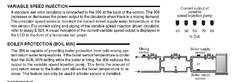
Boiler circulator position. If you are using a mixing valve "termovar / danfoss" don't you want the circulator closest to the boiler on the return line with the mixing valve before it. So, you are pulling the water through the mixing valve and pushing the tempered water into the boiler ? The critical part being that the mixing valve preforms best when the water is pulled through it ?

Air removal. There was a excellent post on this. It described the reason for the location of the scoop / spirovent ( and expansion tank ) to be located prior to the return circulator. The reason was to do with the pressure drop in the line prior the the circulator pump helped release the dissolved oxygen "like taking the top of a soda bottle". This makes perfect sense.
Here's the problem that's not where it's shown on the Tarm instructions nor was that where it was put on my near boiler piping lay out supplied by a third party. Both these layouts have the scoop on the supply (hot out) side of the boiler. Do they do this because of the mixing valve on the return, unlike a generic oil system ?
 
Yes. there is a trade off in that case. I've been taught pump away from a mixing device for best temperature control. In your case this would mean pumping into the return of the boiler.

Air elimination works best at the hottest point, supply from the boiler, and the lowest pressure point. In your case you can't have it both ways, so the air elimination should be up top, at the highest temperature to give you the best result.

I still feel the best option is a delta T circulator instead of a mix valve for return protection.

It allows all components to be in the proper location, removes the "head stealing' mix valve, lowers electrical consumption, and gives you two functions with one device, circulation through the boiler and spot on temperature control to the boiler.

If you chose to go with a high efficiency circ to do this, you may get all this with 30W worth of power. With a mix valve it may cost you 80W or more.
 
I
IHW wrote

" I still feel the best option is a delta T circulator instead of a mix valve for return protection. "

I am not understanding how this works and to set it up.

I am trying to set up my EKO 40 and I know just enough to almost be dangerous.
 
Here is the technical sheet from the tekmar 365 variable speed installation packet. Basically you install the sensor on the return pipe to the boiler. It watches the return temperature and if it drops below, say 150F, it reduces the pump speed.

Reducing the pump speed reduced the flow rate through the boiler to allow the return temperature to increase. Also a drawing on how I piped my EKO 40 to the buffer withy that variable speed pump control. The lower left circ is the one that will get the variable speed control.

hr
 

Attachments

  • Picture 7.png
    Picture 7.png
    21.1 KB · Views: 610
  • Picture 14.png
    Picture 14.png
    22.1 KB · Views: 714
Thanks HR for that explanation. That is a great design.
 
in hot water said:
Here is the technical sheet from the tekmar 365 variable speed installation packet. Basically you install the sensor on the return pipe to the boiler. It watches the return temperature and if it drops below, say 150F, it reduces the pump speed.

Reducing the pump speed reduced the flow rate through the boiler to allow the return temperature to increase. Also a drawing on how I piped my EKO 40 to the buffer withy that variable speed pump control. The lower left circ is the one that will get the variable speed control.

hr

Just catching up on some old threads, and I'm not getting something in your drawing HR - It looks like you have a couple of pumps backwards? There are two pumps on a blue line to the left of the EKO in the area of the storage tank... they appear to be pumping away from the solar heat exchanger, but the arrow on the HX and the pumps on the other side of it seem to suggest they should be pumping TOWARDS the HX, especially the one that is furthest to the left. As drawn it appears that you have two pumps both pulling away from the HX but nothing feeding into it... Am I misreading something, or did you have a thinko? :red:

Looking at it further, I'm not sure the one closer to the boiler is a problem, but I don't quite get why you have two pumps feeding into the boiler like that.

Gooserider
 
Hot Rod,
Can this be accomplished with a circulator such as the 008vdt, or one of the ecm circulators, or is the injection control necessary. I also am about to install an EKO 40, and do not want a Danfoss valve.
Chris
 
Status
Not open for further replies.