Concept Diagram, help and comments welcome

  • Active since 1995, Hearth.com is THE place on the internet for free information and advice about wood stoves, pellet stoves and other energy saving equipment.

    We strive to provide opinions, articles, discussions and history related to Hearth Products and in a more general sense, energy issues.

    We promote the EFFICIENT, RESPONSIBLE, CLEAN and SAFE use of all fuels, whether renewable or fossil.
Status
Not open for further replies.

chrishh

New Member
Aug 21, 2008
14
Western NY
Hello all,

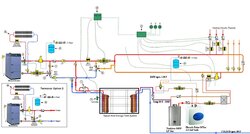
I am by no means a hydronic expert. I have come up with a design for a hydronic/DHW with a wood boiler, thermal storage, and propane backup heat using a tankless DHW heater. Oh also I have added a small point of use electric hot water heater and a circulatory to provide instant DHW. I got some of the design from a Tarm Solo diagram I found on the internet and I got the other part by looking at the Navien System. I'm interested in getting feedback on the diagram. Please point out any parts of the system that would not work or any improvements. As you can see I also need some help with controls. Oh and please keep the lafter to a minimum :)
 

Attachments

  • hydronic piping tankless DHW.jpg
    hydronic piping tankless DHW.jpg
    102.5 KB · Views: 11,190
First thought - if this were mine I'd swap the location of your heating circuits with your storage circuit. If you have your heating loads "first in line" from the boiler suppy you won't need any fancy controls to decide when water should be going to heat loads and when it should be going to storage. It looks like simply swapping the location of your loads (plumbing wise) you'd be able to accomplish this. Just a thought...
 
Might be missing something, but I don't see where the Tankless DHW is tied into the DHW system. Is it only providing supplemental heat to the zones via the plate hx? Is there an aquastat for the dump zone automag? I have my automag plumbed so that the return is on the return line to the boiler circ rather than on the supply side of the boiler circ. This allows the dump zone to function as a zone in an overheat/power-on situation and rapidly radiate excess heat, rather than just operate on gravity alone. I believe there still is sufficient gravity flow through the circ in the event of an overheat/power-off situation. Maybe the Termovar loading unit will not allow this to occur, as I have just the Termovar valve on my system.
 
stee6043 said:
First thought - if this were mine I'd swap the location of your heating circuits with your storage circuit. If you have your heating loads "first in line" from the boiler suppy you won't need any fancy controls to decide when water should be going to heat loads and when it should be going to storage. It looks like simply swapping the location of your loads (plumbing wise) you'd be able to accomplish this. Just a thought...

That's a good point I'll have to toy around with that for a min and see if I can think of any reason why I wouldn't want to do that. Thanks for the input.
 
jebatty said:
Might be missing something, but I don't see where the Tankless DHW is tied into the DHW system. Is it only providing supplemental heat to the zones via the plate hx? Is there an aquastat for the dump zone automag? I have my automag plumbed so that the return is on the return line to the boiler circ rather than on the supply side of the boiler circ. This allows the dump zone to function as a zone in an overheat/power-on situation and rapidly radiate excess heat, rather than just operate on gravity alone. I believe there still is sufficient gravity flow through the circ in the event of an overheat/power-off situation. Maybe the Termovar loading unit will not allow this to occur, as I have just the Termovar valve on my system.

It's funny you say that you might be missing something about the tankless and the DHW system, beacause that is the main part where I think I'm missing something. Let me try to explain what I was trying to do with that.

I'll start with the domestic cold coming in to the house. first it get's "pree heated" through the storage tanks if there is any heat in the tanks. Then it gets dumped into the tankless DHW inlet. Then it goes from the outlet to the inlet of a point of use 2.5 gal electric hot water heater. This 2.5 gal DHW heater is used for to reasons. 1) to provide instant hot water to the domestic loops via a circulator 2) it acts as any buffer to the system to prevent any cold-hot-cold that you can get with a tankless. That's on the domestic side of things. on the heating side the tankless is being used as a source of "backup heat" just enough BTU's to keep the house above freezing. This happens via the circulator connected to the flat plate heat exchanger on the domestic side kicking on and providing heat to the what I will call the zone loop. The only potential problem that I can see here is that I may need to shut down the circulator on the DHW loop because I don't want to be drawing hot water away from the flat plate heat exchanger and mixing cold water with it at the anti scald valve and cooling everything down.

Thanks,


Chris
 
I just wanted to post the goals of this diagram to give everyone an idea of what I was trying to accomplish and to see if anyone already has a diagram that meets all the features that I'm looking to have.

The goals of this system are to provide the following features:

1) 1 burn a day with the wood gasification boiler, reason for the thermal storage. sized for wood boiler and house. aprox. 832 gal. wood boiler 150k BTU 2) An automated system to switch from wood boiler, to thermal storage and then to backup heat while no one is at the residence. 3) combine domestic hot water and wood heat to reduce fuel costs. wood is free at this location. 4) provide instant hot water with circulator pump on domestic hot water side. 5) provide continuous hot water on domestic side. 6) use domestic hot water heater as the backup source of heat for feature #2. Domestic backup to only maintain house temperature above freezing.

Explanation of diagram

B) circuit is a dump zone required by code. C-3) is the heating circuit circulator D) mixing valve to prevent thermal shock to boiler C-1) circulator for zone loops E) Diverting valve used to divert supply hot water up to circulator pump C-1 when running in backup heat mode from domestic and heat exchanger H) Tank temp sensor ZV-1 on thermal tank loop) used to shut off loop when tank temp sensor senses thermal tank at min. temp. Expansion tanks) Each expansion tank is used for when the system is running on wood or backup heat respectively.

Things I may need to change so far.
1) move the circulator on the domestic line to after the anti scald valve.
2) wire control to kick of domestic circulator while on backup tankless heat.
2) maybe move the fp heateachanger to zone loop with closely spaced T's?
 
Status
Not open for further replies.