Conflicting advice on cathedral ceiling install

  • Active since 1995, Hearth.com is THE place on the internet for free information and advice about wood stoves, pellet stoves and other energy saving equipment.

    We strive to provide opinions, articles, discussions and history related to Hearth Products and in a more general sense, energy issues.

    We promote the EFFICIENT, RESPONSIBLE, CLEAN and SAFE use of all fuels, whether renewable or fossil.
Status
Not open for further replies.

ChillyNoMore

Member
Dec 15, 2009
52
WA state
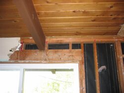
Hi folks. Still trying to get my Scan 61 installed and am so confused about how to do it correctly. The installers I have spoken with say they will use the DuraTech square ceiling support box (9438) to go through the roof/ceiling which is 2"x6” tongue and groove boards spanning exposed rafters that are 6’ on center. (There is also 2.5” of rigid foam insulation above the T&G boards and then probably a layer of plywood topped off with “4-ply hot built-up roof system”.)

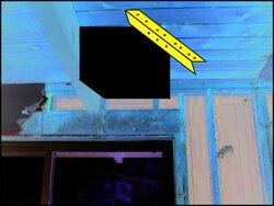
The problem is how to frame in the opening given the exposed rafters. The installers say they will simply cut the sides of the support box above the roof and then fold the resulting flaps down and screw them into the roof deck. However, when I called DuraTech tech support, they insisted that the support framing for the box has to go from rafter to rafter in order to support the weight of the chimney. With the framing exposed as it is, I have no idea how to do this without tearing up 6' of roof or making something really ugly on the inside. I really don't want the chimney crashing through the roof, but is this overkill or not? I would love to hear from anyone who has done a similar install. Thanks in advance.
 

Attachments

  • Framing 007 (Medium).jpg
    Framing 007 (Medium).jpg
    53.9 KB · Views: 832
I can see your dilemma. Here are a few ideas. The main issue seems to be supporting the end of the 2x6tg boards. One solution would be to go out the wall next to the window.

Another solution might be to make a 2x4 collar for the support box that gets anchored to the roof, through insulation and TG boards. This would be with something like 5" decking screws?

Another possible solution would be to use a roof support kit for holding the class A pipe. That would pass a round class A pipe down which would get a trim ring. Before putting on the trim ring I would create a plywood doughnut to hold the TG boards together and try to tie that to the roof with deck screws.
 
Where will this square ceiling support box be in relation to the two nearest rafters? If reasonably centred, you could hang the box with some wrought iron rods tied back to the rafters. If you don't want to take it all the way back to the rafters, you could do bookends with wrought iron shelf brackets.

Where you cut through the insulation, channel it out so you can insert a filler strip of wood that you can then nail the ends of the boards to along with the roof sheathing.
 
how about cutting out 3.5'' of insulation around the box. then cut 2x4 to make the box slid them in under the roof system and take cabinet screws and screw up through the t&g boards. the screws have real small heads so you wont see them to well. then put 1'' of foam on top of the 2x4's so when you put the flashing on it wont settle in that spot and you didn't have to make a big hole in the roof. (no bigger than what you need to get the pipe to code, the 2x4's should fit if you angle them in then hammer straight.)
 
Im thinking that there has to be more to the roof than just t&g boards/foam/plywood on 6 foot centered beams. Especially in Wa state, where the wet snow loads can get pretty heavy, not to mention the weight of the built up roofing. I would think that if the only support beams were 6 foot apart that the roof would sag quite a bit inbetween the beams. Its it possible that there is more to the roof than it appears? are the beams really strucual or are they psuedo beams?
 
I suspect your roof is a structural insulated panel (SIP)....meaning it's a sandwich of wood and foam all adhered together. The entire thickness of wood/foam/wood acts as a structural member, not just the 2x6s alone. One way you can tell is that your photo shows butted ends of 2x6s...if these were structural alone, they'd all end on top of a rafter, not in the bay between rafters.

What you do next depends upon the size hole you're cutting. In theory, a small hole needs no additional perimeter support. A large hole may require adding some framing members below the roof deck, spanning to adjacent rafters.
In either scenairo, if it's a low slope roof, you might consider building a wood curb on top of the roof deck and flash the roof into that. You could also then attach the duratech box to the curb, which is in turn, supported by the SIP.

If your entire home is built of SIPs, it may be extremely air tight and your stove will need an outside air kit.
 
Thanks for the posting elmoleaf. That's helpful information.
 
Thanks to everyone for your helpful comments and suggestions.

Elmoleaf, I will be installing an outside air kit. Today the house is very leaky, but I am tightening it up as I remodel in stages.

BeGreen, I would like to avoid going out the wall to keep more of the stovepipe warm inside. Also, since the roof eaves extend 5' feet, I would still have to cut a hole in the roof.

Regarding the roof construction, the house is a 1960's ranch and the roof (2:12 pitch) was redone 10 years ago. According to the roofing company, the roofing assembly consists of:
- 2"x6" tongue and groove decking
- 2.5" polyiso foam (for R-18)
- 0.5" built-up roofing system (4-ply)

That's it, nothing else, not even a layer of plywood over the foam (much to my surprise). The roofer, like the chimney installer, is saying that all that is needed is a frame of 2"x4"s screwed into the T&G decking. The support box itself is 12"x12" in size, so perhaps this is a small enough hole that I need not worry? DuraTech also makes a reduced clearance support box (9436) that only requires a 10"x10" hole. It has to be special ordered, but perhaps it is worth the effort. Has anyone used one of these?

As for the chimney placement relative to the rafters -- the support box could be flush with or 2" away from the rafter if I decide to use the trim ring. Any opinions on which would look better?

Thanks again for all your help!

Still Chilly
 
I've never heard of skipping the top sheathing. Calling hogwildz to the roofing lobby for a consult.

If possible, I like the idea of the cathedral box being placed up against the ceiling rafter. That gives at least one solid attachment point for the box. No need to go for the smaller box, but do center the support box so the only 2 of the TG boards need to be cut. Given that there is no top sheathing I am thinking the next best thing would to be to take a piece of 1.5" x 1.5" x 24" angle iron for the opposite side of the box. Predrill it to anchor to the uncut 2x6 TG on both ends and to provide a rigid tie for the 2 cut ends of the TG. Also predrill for a couple 10_24 metal screws to attach to the cathedral box. Paint it black and it should look intentional. The other 2 sides of the box can be screwed into the center sides of the adjacent 2x6tg's.

Here's a crude and exaggerated image of what I am trying to describe. The angle iron ends could be ground to a radius for a more finished look.
 

Attachments

  • box with angleiron.jpg
    box with angleiron.jpg
    51.5 KB · Views: 370
I don't know if this helps but I was involved in remodeling the same house design (also 1960's here in the NW with the same T&G ceiling and flat roof.) Yes there is nothing else up there.
I would stand off from the beam as whenever I try to cut something in close like that, I always end wishing I hadn't and waste a lot of time fighting it.
For our 2' x 4' skylite the contractors were able to just cut it in, no extra support needed. See picture. Your stove pipe hole should be no problem, ultimately the pipe weight should be on the stove depedning on how it is installed. More importantly, make sure penetration is flashed and sealed well, preferably by a good roofer and not just someone that just knows how to squeeze gunk out of a tube, those folks are quite common. You're already at a disadvantage being in the NW with a flat roof. Just picture the snow deep around a melting pipe!

As far as the fresh air supply, you might check out http://www.woodheat.org/outdoorair/outdoorcmhc.htm for possible myths regarding their need, especially for a house built in the 60's and even more for your stove and pipe that are completely within the building envelope, your draft should be no problem and I suspect their use might be a net loss on energy. You can always add one later if you're so inclined and feel the need.

Just my two cents.
 

Attachments

  • 149-4924_img.jpg
    149-4924_img.jpg
    28.2 KB · Views: 386
The Class A pipe weight will not be on the stove. The stove will only have the connector pipe weight on it. The support box carries the weight of the Class A. With wind (and snow) loads on this big lever, you want a solid foundation.
 
We have a similar setup in our 50's ranch: low slope roof, exposed beams supporting a fir tongue-and-groove deck, bit of insulation on top (we only have 1/2"!) then roofing material (no plywood).

I sited our chimney just off a beam so that one side of the support box is a couple of inches away from the beam below the ceiling. Similarly, another side of the box is less than a foot off the roof ridgeline which runs perpendicular to the beam (basically as close as we can get and still maintain safe clearances for the stovepipe to the wall). We screwed steel angle strips (not sure of the technical term) -- 1 3/4" x 1 3/4" x 1/4", iirc -- along the top and bottom edges of the opening and all the way onto the adjacent beam, to help transfer the weight of the box + chimney onto the beam using something more substantial than a narrow piece of fir. I suppose we could also have run another piece of steel up to the ridgeline, or continued the header and footer pieces all the way across to the next beam if we were being paranoid. We also have a roof brace for the chimney, to help prevent the lever effect. Our township's building and fire inspectors signed off on this setup. We used a similar scheme for our skylights (on the advice of a structural engineer), except that in this case, the steel went all the way across from one beam to the next, at the head and foot of the skylight. Given that the chimney is a lot less heavy than the skylights, even with wind on it, we didn't take the steel all the way between two beams for the chimney; this also helped minimize the amount of disturbance to the roof.

I totally agree with the point about making sure that you get a good roofer involved (and ensuring they have full insurance). These roofs are not at all easy to flash properly. Our roofer spent a good while making sure the flashing and roof-brace boots were sealed and coated properly.
 
Status
Not open for further replies.