Controlled shutdown from UPS and DDM port

  • Active since 1995, Hearth.com is THE place on the internet for free information and advice about wood stoves, pellet stoves and other energy saving equipment.

    We strive to provide opinions, articles, discussions and history related to Hearth Products and in a more general sense, energy issues.

    We promote the EFFICIENT, RESPONSIBLE, CLEAN and SAFE use of all fuels, whether renewable or fossil.
Status
Not open for further replies.

lapoltba

New Member
Sep 18, 2014
12
06076
I just finished installing my P43 and I intend to hook it up to a true sine wave UPS system. My issue is, I want to be able to tell the stove to do a controlled shutdown before the batteries are completely drained. I know the new stoves have a diagnostic port to connect the Harman DDM tool, but I wanted to know if there was any way to use this port to perform a shutdown.

I'm assuming the DDM is some sort of serial protocol. I was hoping someone had some more info on it. Calling Harman and my dealer was pretty much a waste of time as I expected.

I'm an Electrical/Mechanical engineer and I generally can't leave anything I own alone. My UPS would likely power the stove for 10+ hours, but I want the security of knowing it will shut itself off automatically.
 
I think your out of luck. You will need a modified sign inverter for a controlled shutdown. The control board senses the step square wave through the mains.

The port on the control board only functions to support the DDM (and its not a standard serial protocol). The data appears encrypted.

Been there but for different reason.
 
Last edited:
I connected a low voltage sensor to a relay on my auger motor. When, the voltage drops below a given level, pellets stop feeding, the fire goes out and the stove shuts down
 
I connected a low voltage sensor to a relay on my auger motor. When, the voltage drops below a given level, pellets stop feeding, the fire goes out and the stove shuts down
How do you manage voltage bounce?
 
How do you manage voltage bounce?
I use a 2 pole relay. On pole1, I have the auger motor. Pole 2 is connected in series with the relay coil and the low voltage disconnect. I have a NO push button across the contacts of pole 2. Once the low voltage disconnect opens up and deactivates the relay, it will not reactivate until the button is pushed.
 
Thanks everyone. I'm used to the industrial world where everything has I/O available and is well documented. Tinkering with consumer electronics remains difficult.

I like the auger motor cut out. It is simple enough and accomplishes the same thing. A simple SSR or regular relay connected to my inverter/control logic would work. No worries about voltage bounce. Whatever is sent from the control board through the relay will be identical compared to stock wiring.

I was going to have the inverter/charger hooked up to a microcontroller that would handle the battery voltage monitoring and shutdown of the stove.
 
Maybe you guys could post your details of your solutions for other member consideration?
 
  • Like
Reactions: mralias
I'm only in the planning stages right now. I will definitely post info when I'm done. I haven't decided if I want to go with a true sine inverter/charger combo or separate inverter and charger units with an automatic transfer switch. There are benefits to each. The control side will probably be just a simple Arduino running some code.


I would still like to know what Spock means by "encrypted". I highly doubt they did anything super fancy with it.
 
so thats a "no" then for hyperteminal? didn't think it'd be that easy

This is a sample of what you get off pin 39-PS1/TXD looked at by hyper terminal (using a RS-232 Level Converter) :

ÁÿCOPYRIGHT 2010 HARMAN STOVE [16]þE¿[07][03]©ÿ[01]R[00]»[0F][0F][00][00][0E][00][01][1D][1F]Œ[01][19][01][18][00]CEÀ[01][1A]¥ÖY[00][00][00]¦F[11]ÿ h[00][00]ÿ[00]F[00][00][00][00][00][00][00]E[14].”a[00]ÿ[00][00][00][01][04][01]à'Ï[01][01][00][00][00][01][1D][00]ð[00][00][00][00][00][00][01][00]PÌ[14]ûAA[00][00][00][00][00][00][00][00][00][00][00][00][00][00][00][00][00][00][00][00][00][00][00][00][00][00][00][00][00][00][00][00][00][00][00][00][00][00][00][00][00][00][00][00][00][00][00][00][00][00][00][00][00][00][00][00][00][00][00][00][00][00][00][00][00][00][00][00][00][00][00][00][00][00][00][00][00][00][00][00][00][00][00][00][00][00][00][00][00][00][00][00][00][00][00][00][00][00][00][00][00][00][00][00][00][00][00][00][00][00][00][00][00][00][00][00][00][00][00][00]8 À?[00]Î[0B][00][00]

ÁÿCOPYRIGHT 2010 HARMAN STOVE [16]þE¿[07][03]©ÿ[01]R[00]¼[0E]Ï[00][00][0E][00][01][1D][00][00][01][19][01][18][00]CEÀ[01][1A]fY-[00][00][00]¦F[11]ÿ h[00][00]ÿ[00]F[00][00][00][00][00][00][00]E[14]n” [00]ÿ[00][00][00][01][04][01]à'Ï[01][01][00][00][00][01][1D][00]ð[00][00][00][00][00][00][01][00]PÌ[14]ûAA[00][00][00][00][00][00][00][00][00][00][00][00][00][00][00][00][00][00][00][00][00][00][00][00][00][00][00][00][00][00][00][00][00][00][00][00][00][00][00][00][00][00][00][00][00][00][00][00][00][00][00][00][00][00][00][00][00][00][00][00][00][00][00][00][00][00][00][00][00][00][00][00][00][00][00][00][00][00][00][00][00][00][00][00][00][00][00][00][00][00][00][00][00][00][00][00][00][00][00][00][00][00][00][00][00][00][00][00][00][00][00][00][00][00][00][00][00][00][00][00]8 À¿[00]Î[0B][00][00]

It could be the converter used to convert the serial data to RS232 was not accurate. But as you can see the copyright is in clear text so I am not so sure.
 
I would still like to know what Spock means by "encrypted". I highly doubt they did anything super fancy with it.

I thought that too. See post above. By encrypted I mean it doesn't appear to be a straightforward serial communication. It's almost like they are changing bit widths during transmission or something else. I have tried taking the data and bit shifting it, swap nibbles, reverse bit ,simple XOR's but no sense came from the data. Haven't had time to pursue further (a digital scope would be nice too) to get a closer look.
 
Interesting! I wish I had a unit here to play with and test. You are correct, a digital scope with protocol analyzer would be ideal to sniff communications while playing around. Even still, it may not even have the functionality I am looking for. The simple, quick & dirty approach is stopping the auger motor.

It appears that your display settings in Hyperterm may be interpreting the HEX data and trying to convert it to ASCII? Realterm has a spy mode, but I haven't coughed up the $$ to buy the license. Also, do you know if the coms are full or half duplex? I would be interested in seeing the raw HEX if you have it. It is possible that the commands have differing lengths and the responses have different lengths. If coms are full duplex, you may be seeing bi-directional traffic too I think.
 
As a child, my mother told me I was smart.

I'm beginning to think she lied.
 
Interesting! I wish I had a unit here to play with and test. You are correct, a digital scope with protocol analyzer would be ideal to sniff communications while playing around. Even still, it may not even have the functionality I am looking for. The simple, quick & dirty approach is stopping the auger motor.

It appears that your display settings in Hyperterm may be interpreting the HEX data and trying to convert it to ASCII? Realterm has a spy mode, but I haven't coughed up the $$ to buy the license. Also, do you know if the coms are full or half duplex? I would be interested in seeing the raw HEX if you have it. It is possible that the commands have differing lengths and the responses have different lengths. If coms are full duplex, you may be seeing bi-directional traffic too I think.

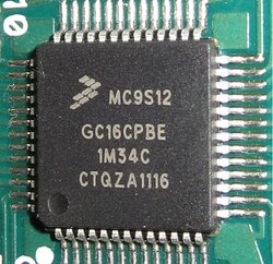
I was converting the binary to ASCII to look for patterns. For example I recorded samples with the auger running then not - looking for the pattern. The data was sampled on the TX (transmit only) pin of the micro.I had thought to that the commands have differing lengths and also that commands, like "turn auger on", may not always come at the same offset in the data packet, not really worth investigating further without the right equipment. The micro has the ability to transmit the flashed code (however it has a lock feature to prevent it) so someone with the right equipment could attempt this and reverse engineer the code. That would tell all.
 
Have Fun !

micro.jpg
 
I needed another project like I need a hole in my head.... I'll poke around a bit when I get home, but unless there is a JTAG header and/or ICSP on the board it will be difficult.

Take the path of least resistance as they say. I always try to leave existing systems in place as much as possible. Working around them for integration seems to cause far fewer problems in the end.
 
If you use one of the Harman approved UPS systems it will do a shutdown automatically and burst the exhaust fan periodically until completely out. I have tested this and it works great. When power is restored you turn the P48 off and then back on to start up again.
 
If you use one of the Harman approved UPS systems it will do a shutdown automatically and burst the exhaust fan periodically until completely out. I have tested this and it works great. When power is restored you turn the P48 off and then back on to start up again.

Thanks, I realize that, but it is not what I am looking for. I do not want the stove to shutdown immediately. I want it to continue normal operation until my battery backup has been depleted to a determined level (battery safe), and then shutdown. I often leave town for the weekend or overnight, and I would like to have the stove running in the event of a power failure.

I hooked up my 700va APC UPS last night and the stove happily runs when I unplug it from the wall.
 
Got it. Look forward to a real solution and would be willing to pay for such a solution.


I don't plan on making a kit or anything. I am happy to share my drawings, schematics, hardware, and any control info for free. I may or may not integrate an Arduino or some other Micro to do some higher level stuff, but I plan to have everything stand alone for the time being.

It certainly won't be a UPS replacement, as I don't care to spend the time getting the switching times down to <10ms and do phase matching. I'm likely going to use a(n) contactor(s) to do the load switching, and they are around 40ms response time. More than good enough for a pellet stove though. I'm still looking around at parts/options but I will update.

Is there a better place in the forum that I should post when I decide to start building?
 
I thought about it in the past. I'd like to trigger an error sensor. like out of pellets, proof of fire, etc at the snap disc circuit somehow to cut everything but the fans with it's OWN circuitry, not my hack. if my hack fails, it would simply shut the circuit, not fry the board by sending voltage.

But i would also like it to only happen when the ups gets to 20% life or something like that, not right away. the timer is the hardest part of it all. on a PC, its the pc software that drives and polls for battery life
 
But i would also like it to only happen when the ups gets to 20% life or something like that, not right away. the timer is the hardest part of it all. on a PC, its the pc software that drives and polls for battery life


That is exactly what I'm thinking. The suggestion above was to just interrupt the pellet feed motor. A simple SPST relay would work and requires very little modification. I read somewhere there is a sensor for the hopper lid that prevents the auger from rotating too. That makes sense for safety. It would prevent someone from chopping their fingers off being stupid. Again, a SPST relay would probably work here. It's likely just a limit switch.

My understanding is that interrupting either of these things will produce a controlled shutdown. Like you said, the voltage sense and control side is the most difficult part. I am trying to source an inverter/charger unit that will handle the load transfer by itself (faster too). At least then I would only have to handle the battery level checking and shutdown circuit. If I can't find one suitable for a reasonable price a separate inverter and charger is the only way to go.
 
My lid sensor doesn't stop the auger.... not sure if I have one or if they never installed it or not but i can leave it open all day and the stove runs.
 
Status
Not open for further replies.