This is kind of a continuation of the https://www.hearth.com/econtent/index.php/forums/viewthread/72159/ thread.
Issue with maximum velocity as specified by copper.org (http://www.copper.org/applications/plumbing/techref/cth/cth_3design_size.html )
Below 140F up to 5 ft/s
Above 140F up to 3 ft/s
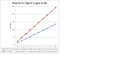
Chart show conversion for type K copper using inside diameter (http://www.sizes.com/materls/pipeCopper.htm ) to find cross sectional area and using 1 cu ft of water is 7.48 gallons (http://dnrc.mt.gov/wrd/water_rts/wr eneral_info/wrforms/615.pdf )
The values agree well with the “Zoning Made Easy†rules of thumb (http://www.bellgossett.com/literature/files/810.pdf ). For example, the 4 gpm quoted in the zoning made easy for 0.75" pipe corresponds to a velocity of about 3 f/s from chart in attached image.
However, using manufacturer specifications for indirect water heater (Amtrol Boilermate http://www.amtrol.com/media/documents/boilermate/9040-586_01_09_BoilerMate_Indirect_IO.pdf – not to pick on Amtrol – I just have one!), the WH-7 series has 0.75†fittings and heat exchanger and the pump curve calls for a minimum of 5gpm flow. The minimum flow exceeds the recommended velocity for the 0.75†Cu fittings on the tank…What is wrong with my math?
PM me if you would like a copy of the Excel 2007 workbook used to generate the attached plot.
Thanks,
Steve
Issue with maximum velocity as specified by copper.org (http://www.copper.org/applications/plumbing/techref/cth/cth_3design_size.html )
Below 140F up to 5 ft/s
Above 140F up to 3 ft/s
Chart show conversion for type K copper using inside diameter (http://www.sizes.com/materls/pipeCopper.htm ) to find cross sectional area and using 1 cu ft of water is 7.48 gallons (http://dnrc.mt.gov/wrd/water_rts/wr
eneral_info/wrforms/615.pdf )The values agree well with the “Zoning Made Easy†rules of thumb (http://www.bellgossett.com/literature/files/810.pdf ). For example, the 4 gpm quoted in the zoning made easy for 0.75" pipe corresponds to a velocity of about 3 f/s from chart in attached image.
However, using manufacturer specifications for indirect water heater (Amtrol Boilermate http://www.amtrol.com/media/documents/boilermate/9040-586_01_09_BoilerMate_Indirect_IO.pdf – not to pick on Amtrol – I just have one!), the WH-7 series has 0.75†fittings and heat exchanger and the pump curve calls for a minimum of 5gpm flow. The minimum flow exceeds the recommended velocity for the 0.75†Cu fittings on the tank…What is wrong with my math?
PM me if you would like a copy of the Excel 2007 workbook used to generate the attached plot.
Thanks,
Steve