corrugated stainless for in tank HX

  • Active since 1995, Hearth.com is THE place on the internet for free information and advice about wood stoves, pellet stoves and other energy saving equipment.

    We strive to provide opinions, articles, discussions and history related to Hearth Products and in a more general sense, energy issues.

    We promote the EFFICIENT, RESPONSIBLE, CLEAN and SAFE use of all fuels, whether renewable or fossil.
Status
Not open for further replies.

pybyr

Minister of Fire
Jun 3, 2008
2,300
Adamant, VT 05640
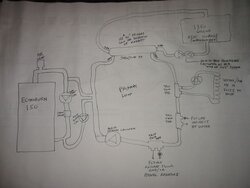
I'm still plugging away at planning my system, and will definitely have an unpressurized 1350 gallon tank

I've been been leaning towards a plate HX, but got thinking back to the Haase tank assembly videos I saw on YouTube (based on someone's post here several months back), which had me thinking about how the Haase uses internal nested spirals of corrugated stainless tubing

I know that corrugated stainless tubing is used for natural gas and propane piping ( "csst" )
http://www.gastite.com/include/languages/english/downloads/pdfs/ES-CSST.pdf
, and got to wondering whether anyone ever considered using it as an in-tank coil, rather than the "usual" copper or some folks (like sparke)'s use of PEX

is it just that the price is painfully high for the material (I have not gotten too far in looking at price, as I first want to know if there's some other downside I haven't thought of) ?
 
If the tubing is not plastic coated, I don't see why i would not work. Copper transfers heat faster than stainless. I would assume stainless will transfer faster than pex?
 
I think CSST might be more expensive per foot, but the corrugations do add surface area. I say go for it and let us know how it works out.

Chris
 
I noticed that you have a 2nd similar post with info on sizes, prices, and more.

After thinking last night, I'd like to add that I would imagine that the interior corrugations would cause turbulence and would slow down the flow. I'm not an engineer, maybe someone here is? For lack of better knowledge, I might would go a size larger than the intended tube size from the pump?
 
Slowing down the flow will increase the rate of heat transfer as will the corrugations. If you can afford the stainless go for it .
 
Automatic transmission coolers are "corrugated " on the inside. For those that haven't seen one they usually are a hollow tube of brass. Inside the tube around the outer circumference is a thin sheet of brass that is punched with holes in a way to provide turbulence. On the same idea as a cheese grater. This is where the tranny fluid travels either giving up its heat or in the case of extremely cold weather taking some heat on for proper tranny operation.
Will
 
it seems that the corrugated stainless tubing is available in many diameters, and as several folks here have noted, the corrugations will increase surface area, and slow the flow, which seems good for heat exchange

that also raises the interesting question of whether this (corrugated stainless) could be used in an HX coil arrangement with a much shorter overall length of much larger-diameter tubing than with the "usual" HX coil of 1/2 or 3/4 smooth-wall pipe.

I see that corrugated stainless tubing can be obtained in all sorts of diameters:
http://www.precisionhose.com/cmh_bwach.htm
(don't know prices yet)

I recall that someone commented here in one of the threads that going too large in tubing diameter (with usual smooth tubing) in a heat exchange coil has the effect of creating too much laminar flow, which'll lead to too little contact of the overall net volume/ flow of water with the outer wall of the tubing where the H/X takes place- that makes sense-- but the corrugations plus the spiral would (I think?) create all sorts of turbulence, allowing much larger tubing diameter (like 1&1;/2 or 2 inch) and shorter overall length while still having most of the water have a lot of contact with the walls

any reactions or suggestions in regard to that idea?

I also recall looking in some of the other homemade HX coil threads here and seeing that people were kicking around a ballpark of needing about 4000-5000 square inches of surface of copper tubing to successfully transfer the heat output of a boiler in the 140-150,000 BTU/hr range. Has that been generally verified and accepted by either math or experience?

And can someone help shortcut me to a location that will let me compare the heat transfer rate/ effectiveness of stainless compared to copper?

I haven't ruled out a plate HX arrangement, but do still at times find myself coming back to the appeal of an in-tank coil allowing elimination of some circulators and plumbing complexity, and less worry/ complexity of needing to avoid having direct flow into and out of the tank foul up the stratification-- which is what has me giving the corrugated stainless one last look-- and the large diameter of the coils might allow me to use really modest-sized circulators for the tank's loop, which'd reduce up front cost and operating cost

thanks for helping me kick all these possibilities around- and I appreciate all the sharing of ideas and experience here
 
Corrugated stainless is used in several tank products. I'm a fan.

One downside: you can't just solder the loops to a vertical piece of copper tube to keep them spaced evenly, like you can with copper. Need a stainless strip (preferable with pre-punched holes, for simplicity), and some stainless wire to tie the loops to the strip to keep them from just falling to the bottom.

Joe
 
Thanks for the comments Joe- I realize that there'd need to be some supports, and I have some ideas for those- do you have any comments or suggestions on a ball-park optimal balance between tubing diameter and HX length to "sink" 150kBTU into a 1350 gallon tank without boiler idling?

Thanks
 
pybyr said:
Thanks for the comments Joe- I realize that there'd need to be some supports, and I have some ideas for those- do you have any comments or suggestions on a ball-park optimal balance between tubing diameter and HX length to "sink" 150kBTU into a 1350 gallon tank without boiler idling?

I'd stick with 3/4" pipe, personally. It's going over that is going to impact heat transfer by establishing a larger laminar area in the center of the pipe. Run parallel loops to cut down on head loss. In other words, run two or three coils of pipe, with all the top ends connected together and all the bottom ends connected together.

I've not actually done any designs with it (I just like it as an idea), so I can't tell you exact lengths. I believe it ends up being similar to copper - the stainless doesn't transfer as well ber square foot, but the corrugations increase the surface area and the turbulence, so that tends to balance it out.

Personally, I still prefer plate heat exchangers. By the way, I sent you an email on that subject, earlier today.

By the way, for bare CSST pipe, this is one source, which also includes specs and such: http://www.omegaflex.com/stan.htm

Joe
 
BrownianHeatingTech said:
Personally, I still prefer plate heat exchangers. By the way, I sent you an email on that subject, earlier today.

Joe

Hi Joe- I got your e-mail asking for details about my tank, which I am about to send you by e-mail, but I am not finding one about plate exchangers, if that is what you meant. If you sent me something about plate exchangers, could you please re-send?

I am really on the fence about the "coil in tank vs plate HX" as each seem to have distinct merits, so if you have further points, I welcome them.

I still think the idea of having the plate HX right _in_ my primary loop, as someone else here on the forum suggested, and if it could be done without too much flow restriction, would be the bee's knees. and the best of both worlds. So far I am just too far over my head on the details of the variables and calculations to get to the bottom of whether there are products available (and that are affordable for a homeowner-type project) that would allow that. I know my way around physics on a conceptual level, but lack the depth of training in the really "hard math" end of applying it in the engineering for a specific set of conditions
 
pybyr said:
Hi Joe- I got your e-mail asking for details about my tank, which I am about to send you by e-mail, but I am not finding one about plate exchangers, if that is what you meant. If you sent me something about plate exchangers, could you please re-send?

Oh, the plate heat exchanger part was the ease of connecting pumps below the waterline with that tank design, without having to use dip tubes or penetrate an EPDM liner. Similar advantage to pressurized storage, but without the need for an expansion tank.

pybyr said:
I still think the idea of having the plate HX right _in_ my primary loop, as someone else here on the forum suggested, and if it could be done without too much flow restriction, would be the bee's knees. and the best of both worlds.

A shell-and-tube heat exchanger would be good for that application. There is very little pressure drop on the shell side, which is what you would use for the primary loop.

Joe
 
BrownianHeatingTech said:
[
A shell-and-tube heat exchanger would be good for that application. There is very little pressure drop on the shell side, which is what you would use for the primary loop.

Joe

I like the idea of a shell-and tube and get your point, and have even done a bit of preliminary looking around at what I could perhaps scare up surplus or something, but am at a loss of where to even start in terms of sizing a shell-and-tube to the heat transfer I am looking to achieve.

Unlike the flat plate HXes where manufacturers seem to give BTU figures for residential hydronic applications, it seems like the shell-and-tube exchangers are aimed at industrial applications, and so the specs seem to assume that the customer/ designer has some analytical and application horsepower far beyond mine in selecting the "right one" for a particular job. Can you offer me any pointers?

Thanks again for the help and insights
 
Joe

Can you share with all of us what you mean by "the plate heat exchanger part was the ease of connecting pumps below the waterline with that tank design, without having to use dip tubes or penetrate an EPDM liner." Also, what tank design is being referred to. Thanks
 
WoodNotOil said:
Joe

Can you share with all of us what you mean by "the plate heat exchanger part was the ease of connecting pumps below the waterline with that tank design, without having to use dip tubes or penetrate an EPDM liner." Also, what tank design is being referred to. Thanks

Joe was asking me about/ referring to my forthcoming "overkill special" sectional stainless tank that I've mentioned here on Hearth

I too am interested in his thinking on locating and plumbing the circs

it's great how the many minds around this group come up with ideas that assist and enhance each other
 
I keep jumping back and fourth between flat plate and coils but with that fancy ss tank and a few tappings on the bottom
it would be easy to use a flat plate.
I have had various ideas some maybe good some not so good, so maybe joe could offer some input on this idea?

here are the numbers for a 5x13 40 plate ex.

Model: FG5X12-40(1-1/4"MPT)
Selection IDNUB7W4T3T Model size5x13
ApplicationLiquid to liquid Nominal surface (ft²)14.6
Load (Btu/h)146,482 Dimensions5.1W x 13.3H x 3.9D
Log mean temp. diff. (°F)10.0 Plate constructionSingle wall
Overall HTC (Btu/h·ft²·°F)1,017 Net weight (lb)15.9
Oversurface percent1.1
Design Conditions Side A - Liquid Side B - Liquid
Fluid type Water Water
Fluid mass flow rate (lb/min) 121.9 122.0
Entering fluid temp. (°F) 180.0 150.0
Leaving fluid temp. (°F) 160.0 170.0
Fluid flow rate (GPM) 15.0 15.0
Fluid fouling factor (h·ft²·°F/Btu) 0.00010 0.00010
Model Parameters
Number of channels 19 20
Velocity (ft/s) 0.75 0.71
Pressure drop (psi) 1.7 1.5
Heat transfer coef. (Btu/h·ft²·°F) 2,618 2,492
Internal volume (ft³) 0.057 0.060

Ratings at Varying Conditions

Percent difference -15% -7½% 0% 7½% 15%
Pressure drop (psi) (Side A) 1.2 1.4 1.7 1.9 2.2
Pressure drop (psi) (Side B) 1.1 1.3 1.5 1.8 2.0
Load (Btu/h) 124,510 135,496 146,482 157,468 168,455
Fluid flow rate (GPM) (Side A) 12.8 13.9 15.0 16.1 17.3
Fluid mass flow rate (lb/min) (Side A) 103.6 112.8 121.9 131.1 140.2
Fluid flow rate (GPM) (Side B) 12.7 13.8 15.0 16.1 17.2
Fluid mass flow rate (lb/min) (Side B) 103.7 112.9 122.0 131.2 140.4
Entering fluid temp. (°F) (Side A) 180.0 180.0 180.0 180.0 180.0
Entering fluid temp. (°F) (Side B) 150.0 150.0 150.0 150.0 150.0
Leaving fluid temp. (°F) (Side A) 160.0 160.0 160.0 160.0 160.0
Leaving fluid temp. (°F) (Side B) 170.0 170.0 170.0 170.0 170.0
Oversurface percent 9.1 4.9 1.1 -2.3 -5.4

1.7 psi pressure drop @ 15 gpm
Instead of an 0012 or some such monster pump why not a pair of 00R's or comparable in parallel and put the flat plate in the primary loop.
pumps would be way cheaper plus one pump failure would not leave you without heat, just reduced capacity untill it could be replaced.


pybyr has given me all sorts of new ideas after I thought I had this all sorted out.I have been back and fourth on the great heat exchange debate so many
times................HEEEEELP. LOL.
 
pybyr said:
I like the idea of a shell-and tube and get your point, and have even done a bit of preliminary looking around at what I could perhaps scare up surplus or something, but am at a loss of where to even start in terms of sizing a shell-and-tube to the heat transfer I am looking to achieve.

Unlike the flat plate HXes where manufacturers seem to give BTU figures for residential hydronic applications, it seems like the shell-and-tube exchangers are aimed at industrial applications, and so the specs seem to assume that the customer/ designer has some analytical and application horsepower far beyond mine in selecting the "right one" for a particular job. Can you offer me any pointers?

The "residential" shell-and-tube heat exchangers tend to be marketed as swimming pool heaters.

How many btu's are you looking to transfer? The full output of the boiler, or will that be on a different loop?

WoodNotOil said:
Can you share with all of us what you mean by "the plate heat exchanger part was the ease of connecting pumps below the waterline with that tank design, without having to use dip tubes or penetrate an EPDM liner." Also, what tank design is being referred to. Thanks

pybyr's stainless tank. As an unlined tank (just metal), you can weld fittings below the waterline, and connect pumps there.

Joe
 
BrownianHeatingTech said:
[The "residential" shell-and-tube heat exchangers tend to be marketed as swimming pool heaters.

How many btu's are you looking to transfer? The full output of the boiler, or will that be on a different loop?

Joe

If at all possible without prohibitive expense, I'd like to be able to send the full output of the 150kBtu Econoburn boiler (without periods of idling) into the tank (this is assuming the situation of a tank that has cooled to the point where it is no longer hot enough to be useful for heat, and "needs a charge") even when the house is not calling for heat.

My thinking in wanting to be able to do that is that there'll be times during spring and fall when the opportunities when it will be convenient for me to run a fire to heat the tank won't necessarily be the same times that anything in the house is calling for heat. Ditto, but even more so, if I end up using the system for DHW in summer.

as to configuration of loads/ loops, what I would like to do is a primary/ secondary system where the boiler is on one secondary, and the heat load to the house is on another secondary (which in the short term will be a water to air HX in the oil warm air furnace plenump- but in the longer term may include radiant floor and/ or panel radiators)(so I'll want to include some extra ports off the primary for future potential secondaries).

Then the tank and its HX, of whatever type, plate, coil, or shell and tube, need to be in the primary between the boiler and the house's heat loads, so that the tank can become a sink downsteam from the boiler when that's most needed or useful, or a source, upstream from the heat loads, when that is most useful. At times when I need to heat a cold house fast, the system could be set to have the primary send heat past the tank straight the thr house's loads

I am still very open to having the tank be its own secondary, tied in via a plate HX (or coil HX in the tank) and Taco Twin Tee (making it easier to reverse flow in the secondary without having to reverse flow in the primary) if that ends up making most overall sense, but the idea of having the HX as an integral part of the primary loop seems like an elegantly simple and straightforward approach.

I was in fact originally thinking of having the tank (via an in-tank coil or plate HX) then be its own secondary - -then Kabbot proposed the really smart idea of having the HX be a unified part of the primary loop. With the order of these being boiler -> tank-> heat loads, in decreasing order of need for high temp.

Did I articulate that in a way that makes it useful to follow in terms of the sizing and location of the shell and tube?

I am going to have the day off tomorrow and am going to spend the morning cutting White Ash; in the afternoon orf evening, I'll try to sketch out my concept of the plumbing and post a photo here on Hearth so that the hoped-for method to my madness might be easier to follow ( or deflate if I am really off the rails somewhere in all this)
 
PS, I have seen the shell and tube units marketed, as you say, Joe, for pools; what I can't figure out yet is how they'd equate - sizing/choice-wise- to this application of trying to heat a much smaller volume of water (than a swimming pool) very hot, very fast.

I also see some surplus shell and tubes on-line, and some of those look promising in concept ( being industrial, they look it, compared to the swimming pool heaters) but again, am floundering on how to assess what I'd need for a minimum surface area (of shell/ tube contact) and length to get the heat exchange I need with my planned temp differentials and likely GPMs from the 150kBTU boiler's primary
 
I'll get back to you with sizing a bit later.

Basically, the question on how many btu's would matter if the storage tank and the boiler were both on the same side of the heat exchanger, so that they could transfer heat directly, and the heat exchanger would only have to transfer the btu's needed by the zones.

Of course, with open storage, that would only work if the storage tank was further isolated by a plate heat exchanger or somesuch.

Once you get your diagram posted, it will be easier to work with.

Joe
 
Actually, looking at the sizing, a large flat plate will be more cost effective. You're right in the size where it's your load is too large to use a small heat exchanger, and jumping up to a larger commercial unit would be too expensive to justify.

Something like a TriangleTube TTP4-50 would work. Alternately, a couple smaller plate heat exchangers in parallel would be an option, if they are more readily available.

Joe
 
Thanks Joe- I've been out in the woods cutting (found an area with way more standing dead eastern hornbeam than I'd even realized - some of them unusually big- and it's like having a party- almost no limbing, and the stuff is dry as a bone and not rotten)

I came in for lunch and am checking here briefly. I really appreciate your suggestion, but when I googled pricing on the Triangle Tube you mention, I nearly fell over- list of $2k plus just for the HX

When I look on eBay I am seeing some industrial surplus shell and tube exchangers that, although not cheap, are way less than the big Triangle Tube plate you mention- if they'd work, and that's where I fall into the puzzlement (there's all different diameters and lengths, and one pass vs two vs 4)

Right now I am heading back into the woods. Later on, once I come in from the woods, I will try to sketch out & photograph my conceptual plumbing layouts- there's actually two variants I am considering, and posting them on here, so that it's easier for people to follow what I am actually trying to do.
 
OK, here's my try at drawing and posting a diagram of the plumbing of what I would like to achieve with an unpressurized tank, a shell-tube HX as a direct part of the primary, as suggested by Kabbott, and back-to-back reversible flow circulators as pionneered by WoodNotOil and others on here

I am not a draftsman, nor is my penmanship very good, but I hope this comes through well enough to get feedback.
 

Attachments

  • Trevor's piping diagram for Econoburn and P:S & Shell: Tube HX.jpg
    Trevor's piping diagram for Econoburn and P:S & Shell: Tube HX.jpg
    28.3 KB · Views: 266
pybyr said:
I came in for lunch and am checking here briefly. I really appreciate your suggestion, but when I googled pricing on the Triangle Tube you mention, I nearly fell over- list of $2k plus just for the HX

That's why I suggested that two smaller heat exchangers might be a better idea :)

pybyr said:
OK, here's my try at drawing and posting a diagram of the plumbing of what I would like to achieve with an unpressurized tank, a shell-tube HX as a direct part of the primary, as suggested by Kabbott, and back-to-back reversible flow circulators as pionneered by WoodNotOil and others on here

Okay, some notes:

Use IFC circulators on the Econoburn side, and delete the check valve in the bypass.

Leave a simple air vent on the top of the Econoburn, but install a microbubble remover in the primary loop, after the tees where the Econoburn connects. Plumb the expansion tank into the bottom fitting on the microbubble remover. Install the primary loop circulator after that (but before the tank heat exchanger). If you do end up going with a flat plate heat exchanger, you want the components in that order (boiler - air/expansion - pump - HX) to prevent low pressure pockets in the heat exchanger, which can cause cavitation.

The twin tees for the indirect should be first, so it gets the hottest water once you install it. No need to be taking cold showers.

I would suggest going with a reverse return piping scheme on the zones. That gives them equal access to the temperature in the loop. If you are sure you will go with in-floor radiant, and the design temp is significantly lower than the return temp from the air coil, then the twin tees will be fine. If you use panel radiators, or the design temp for the radiant is higher than the minimum return temp from the air coil, then the radiators/radiant will suffer in performance. In other words, delete the twin tees (except the one used for the indirect), and install four regular tees (supply, supply, return, return). That way, neither zone's supply is pulling return water from another zone. While you're at it, put in another pair of tees (three supplies, then three returns) - tees are cheap, and who knows if you will need to add another zone in the future, so having a pair of plugged tees would be helpful.

Joe
 
Status
Not open for further replies.