Econoburn EBW 200 Install

  • Active since 1995, Hearth.com is THE place on the internet for free information and advice about wood stoves, pellet stoves and other energy saving equipment.

    We strive to provide opinions, articles, discussions and history related to Hearth Products and in a more general sense, energy issues.

    We promote the EFFICIENT, RESPONSIBLE, CLEAN and SAFE use of all fuels, whether renewable or fossil.
Status
Not open for further replies.
My welder cannot come to change my tank fittings until later next week.

If you have a 3/4" fitting in the top of each tank that could well be entirely adequate. Your only talking maybe 15 gpm maxed out, which is only 5.5 feet per second through each fitting. Normally with a deltaT of 40 degF and a realistic boiler output of 175,000 btu per hour the flow through each 3/4" fitting would be less than 3 feet per second.

With 1 1/4" piping in the rest of the circuit, the added resistance would not amount to much at all. To be clear, I'm not suggesting that you run 3/4" inch pipe for the whole circuit, I'm just saying that two short 3/4" restrictions in parallel won't matter.

Some will warn of mixing from jetting the hot water in at the top, but I've come to the conclusion that that may not be such a big deal at all. While storage is filling there would normally be plenty pure hot water left over to satisfy loads. And by the time storage is completely filled the whole tank will be hot top to bottom, so some mixing at the top is mox nix.

When drawing from storage the smaller fittings at the top would be irrelevant.
 
Last edited:
Thanks ew. I removed my upper supply line today and plugged the holes.
Right now I have no fitting in the tops of the tank so I thought that I might as well cut the new openings 1 1/4 inch as the pipe coming from the boiler is also 1 1/4 . After my tanks everything changes to 1 inch. From your comments I should be good with that sizing, which is good to know as I never did the math when I set things up.
I'm not sure I understand what you were saying about mixing in your last paragraph. The way my piping will work is that if the loads are calling for heat the hot water from the boiler will bypass the tanks until the load is satisfied. After that it will heat the storage.
 
I'm not sure I understand what you were saying about mixing in your last paragraph. The way my piping will work is that if the loads are calling for heat the hot water from the boiler will bypass the tanks until the load is satisfied.
I was just noting that if there were existing 3/4" fittings, and if you chose to go that route, then there would be no turbulence problem when drawing out of storage after the boiler heating cycle was done. Turbulence at the top would only be a problem, although negligible, when filling storage.

Although you would want fittings at the very top for air venting, the big ports for the pipes coming from the boiler don't have to be all the way up. Of course any volume above the ports will be lost for the purposes of storing heat, but as you go up the slope towards the center of the dome the volume above the ports drops off very quickly, so if you want the ports more towards the front of the tanks you can do so without giving up a lot. I wish I had done this since working up in there near the rafters was pretty awkward for me.

I ran 1/8" pipe up to a high point above storage and then to the outside of the insulation, which allowed me to do away with any air separator or scrubber. I bled it off when starting up the system and again a month later and since then all I get is water. With the boiler next to storage and with the top of storage above the boiler then the air can only go one place.

Also although I've only ever set up one set of tanks, I must say found it convenient to dry fit everything and then tack the fittings in place before the final welds were done. Then I took it apart enough to cut a hole in the tank with a hole saw inside the fittings after the fittings were in place. Forged steel half couplings (not cast) work very well for fittings.
 
Last edited:
  • Like
Reactions: Boardroom
Maybe you guys are talking about the same thing as I am thinking, but you're saying it in fancy boiler-speak. Isn't it posssible to install a normally open held closed valve at the top of the tank where the hottest water is and plumb it to one of the largest heat load zones. When the power goes out, the NOHC valve opens and gravity (thermosiphon) takes over and shunts the heat load to the zone as the fire dies down in a grid-down situation. Like I said, I'm no boiler expert, but I did stay in a Holiday Inn Express last night........Okay....I didn't really.. I'm just left with not being a boiler expert.........sigh......
 
The type of heat dump you are referring to with the NO valve should be installed directly above the boiler, before storage. There is no need to run it off the top of the storage as your storage has already acted as a zone and absorbed the heat, providing it was not fully charged to start with.
 
I ran 1/8" pipe up to a high point above storage and then to the outside of the insulation, which allowed me to do away with any air separator or scrubber. I bled it off when starting up the system and again a month later and since then all I get is water. With the boiler next to storage and with the top of storage above the boiler then the air can only go one place.

ew - I plan on doing the same thing. I will run a pipe from the top of the tanks to a vent above the insulation. I had only planned to use an air separator because my install manual called for one. Your thinking seems logical in that the air only has one place to go, the top of the tanks. So what If I don't remove it before it gets to the tanks.
The top of my tanks is the high point in my system. Well, maybe some rads in the second storey of my house are actually higher but I can bleed them from there.
I have a good bit of room above the tanks to work in so I may still put the fittings right on top.
 
Guess I still need to figure out the whole quoting thing. Sorry about that.
 
I guess I was thinking of a worst case scenario. If the storage is up to temp and there is still fuel in the boiler, I would want to dump that thermal energy, right? Eventually I want swap out my OWB for a gasser. So I'm still learning the tricks of the trade.
 
I know what you mean about learning. This is definitely the place to do it. Lots of good input on this site from members much more experienced than I.
You are right when you say you would need to dump the thermal energy. The question is what is the best way to do it. If the energy is in the boiler, the best, quickest place to take it from is directly from the boiler, not the storage. Not sure if you have ever seen the Caleffi Idronics 10 book but it is the bible for me on my install. Just google it. You will find the answer to your heat dump question.
 
Hey Goosegunner, you around?
Or anyone else that runs an Econoburn 200. I see some guys use a barometric damper and some don't. Comments on yes or no and perhaps if one damper is better than another?
 
I use one and have a Dwyer manometer that shows draft all the time. I keep it within the draft specs stated by Econoburn. It serves its purpose but I have seen nice ones posted on the board. They seem to be from Europe.

I put a screen and safety stop on mine for back puffs. They can be greatly reduce if you do not split wood real small. I have found the playing card size split is too small for my boiler, some small pieces yes but larger 6 to 8 inch face seem to work better.

gg
 
Thanks gg. What is the model number of your Dwyer?

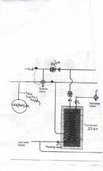
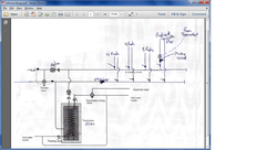
I am also having issues with my inhouse design and could use some input. The below picture is just a slice of where my line comes into the house. The heating loads are all to the right and I have no issue with them.
My problem is the way to hook in the combomax electric boiler. In the picture the diverter valve decides whether to send return water from the electric boiler back to the top line or back out to my tanks. If the return water from the combomax is warmer than my tank water coming in then it will push the combomax water back to the loads instead of using my tank water.
The problems I see are:
1. when I am away my underground line will not flow.
2. my tank water is of no use if it is not above the combomax temperature.

Does anyone see another way to solve this or is this way preferred?
Thanks.

inhouse design_0001.jpg
 
Having a hard time figuring the diagram out.

Does that diverter valve also act as a mixing valve to mix down the hot water before it goes to loads? Or does it just divert?

Is the wood boiler & storage on the left of the diagram, & loads on the right?

Going by the triangles in the circ symbols, looks like the 'alpha' up top is pumping left to right, but the one on top of the electric boiler is pumping down?

If it just diverts - I think you can do what you want by eliminating it, and using checked circs (as long as that one on top of the electric is pumping up). Mine is sort of like that - when there is a call for heat & the system water is too cool, it disables the main load pump & kicks on the electric boiler & its circ. Check valves confine the electric boiler flow to just the zones so it doesn't go thru storage. Not sure I can fully explain my controls - I just lifted all the aquastats off my old wood/oil boiler and transferred them to my new system, and the stat control that used to turn on the oil burner in those conditions now activates the electric boiler thru a relay to the t/t terminals on that. The electric boiler then controls its circ on its own.
 
On the bottom of page 1 of this thread there is another diagram showing the loads and a bit more of an explanation. My rads will all have TRV's on them.
Yes, wood boiler and tanks are to the left and loads to the right.
The diverter valve was just to divert, not mix.
The pump above the electric boiler is pumping down and is controlled by an aquastat on it to supply it with preheated wood boiler water, just like a secondary circuit. All the diverter does is take the water coming out of the electric boiler and decide whether to recirculate it or send it back to the tanks, depending on the temperature. If my tanks are hotter, it will use that water. If they are cooler it will recycle the electric boiler water.
I will put some more thought into your suggestion tonight. At work now and tied up.
 
Well, it took a while for my welder to show up but he was free so I can't really complain.
Thanks to all who provided input regarding the position of the supply pipe on my tanks. I had them moved to the very top. I think it will be well worth the bit of extra trouble it took to do it.
Given that my rise from ground to supply pipe is about 9 feet now, I switched to the Caleffi 281 loading unit. I think I should have enough thermosiphon now to make it work as the heat dump. If it doesn't, you can see that I have left a ball valve on the top of vertical rise from my boiler in case I need to add a NO valve and a rad for a heat dump in the floor above. I ran out of pipe today so you have to imagine a horizontal piece that attaches the top two lines.
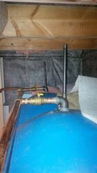
I also added a pic of the fittings at the top of the tanks. Auto air vents will be mounted on the top of the 1/2 inch pipe.
I would love if you guys could have a quick look at things and tell me what you think before I solder it all together.
My big question is this - In my house I have a Combomax electric boiler that will have an air separator above it. The Combomax shares the same boiler water that is in my tanks and my wood boiler. So do I need an air separator above my wood boiler too or is one in the system enough?
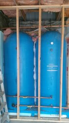
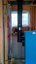
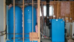
IMG_20141004_135823.jpg IMG_20141004_135803.jpg IMG_20141004_135926.jpg
 
I should have also mentioned that the two open tee's above the boiler are to accommodate the boiler aquastat and a low water cutoff.
 
Hey Goosegunner, you around?
Or anyone else that runs an Econoburn 200. I see some guys use a barometric damper and some don't. Comments on yes or no and perhaps if one damper is better than another?
I have a damper on mine,i also have the back up oil boiler feeding into the same chimney as the 200.The damper is in the pipe from the oil boiler.
Thomas
 
I finally finished my piping in the garage. Here is a photo. I think I should be good to go out there. Just have to pressure check it all. My pump is the Caleffi 281 loading unit.
IMG_20141013_153647.jpg

However, I am really struggling with my in-house design. I had originally posted this picture.
in house design.png

My boiler and tanks are to the left of the photo. I plan to control my rads with individual TRV's

The diverter valve controls the return water from the combomax boiler. If the storage tanks are hot enough it will send the combomax return water back out to the boiler. If the tanks are cool the combomax water will be recycled back into the system.
Maple, thank you for your first reply. You had suggested that I may be able to get rid of the diverter valve and use checked circulators if the pump on the electric boiler is pumping up. Can you detail that a bit more for me please? What line would the electric boiler be drawing its water from? Remember that the combomax boiler does more than heat water for the heating system. It also acts as an instantaneous hot water heater for the domestic hot water. If I pump up then am I not always heating my DHW with electricity? If I pump down, I think it would be like having the combomax as a secondary circuit.
Is anyone else out there using this kind of electric boiler?
Boardroom.
 
If you message ('conversation') me your email address, I can email you an early PDF of my system design that shows how my electric boiler is plumbed. But I don't use mine for DHW - I have an ordinary electric hot water heater for that. So not sure on that part.
 
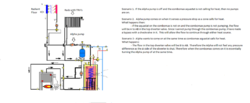
Thanks Maple. Between your ideas and some old posts from Goosegunner regarding pump bypasses, I have came up with the following design.
I put a bypass, with a check valve, around the Armstrong Astro 30 pump that comes installed on the combomax because I wasn't sure if I could pump through it.

Darn- I just saw something . If my radiant floor pump is asking for heat, the Alpha will start up. But what if the A side of the top diverter is closed? The radiant floor pump will be pumping against pressure created on the return manifold. I suppose I could use a zone valve instead of a circulator on that loop or another Alpha but the existing loop is already installed and I would rather not change it. Also, I think the Alpha in the diagram may already be overworked. Can I somehow just have the radiant floor loop circle back on itself in this case?
Boardroom.

total design 2.png
 
Status
Not open for further replies.