EKO hydronic setup. take a look? (revised pressurized storage system design)

  • Active since 1995, Hearth.com is THE place on the internet for free information and advice about wood stoves, pellet stoves and other energy saving equipment.

    We strive to provide opinions, articles, discussions and history related to Hearth Products and in a more general sense, energy issues.

    We promote the EFFICIENT, RESPONSIBLE, CLEAN and SAFE use of all fuels, whether renewable or fossil.
Status
Not open for further replies.

88rxn/a

Member
Feb 12, 2008
145
northeast PA
so i basically took nofosill's sticky thread and thought it through and seen how it would work in my house/future setup. all i did was move the storage to the shed instead of having it all together. i separated with a line to show what im thinking. i didnt move the large expansion tank because i forgot but its supposed to be in the shed also.
my question is, will this way work? im just wondering how i could pull heat from the tanks when the boiler goes out? i havent thought through the wiring yet because im unsure how it all works but i did by this book and just waiting for it to arrive.
http://www.heatinghelp.com/shopcart/product.cfm?category=2-41

any input appreciated.
thanks.

BTW, between the shed and house will be about 55-60 feet of 1 inch PEX or larger depending on the heat load i will need.
 

Attachments

  • toms storage idea.gif
    toms storage idea.gif
    18 KB · Views: 369
Some questions and thoughts. With just the wood circ running maybe a Grundfos 15-58 on speed 2, 12 gpm of flow. How many gpms go through the first storage? How many through the second? what regulates that flow?

If the wood circ and the load circ run at the same time, and they are the same pump, you now have the two circs in series, about 12 gpm at 20 feet of had available through the zones. I would suggest a pressure activated bypass valve be piped in to shed some of that head or those zone valves will see some very high velocity, potentially. Not knowing what is in those baseboard circuits for pipe diametse, length, fittings, etc. Depending on the zone valve type and brand they may not have enough shut off pressure to handle those pumps in series. You may bleed through the valves under some conditions. Although it is unknown how much goes through the tanks and how much to the load circuits. Ideally flowsetters would be installed on the two tanks to "set" that flow rate. Then you would have some stable numbers to design the rest of the system around.

Really no need for two expansion tanks and connection points. You'll just confuse the hydraulics by having two PONPC's. I'd suggest an air purger before the load circ. It's the highest temperature point and the best place to remove air from the system. Also connect the, or multiple, expansion tank and the fill valve at that connection. The point in the system where you install the expansion tank becomes the PONPC (point of no pressure change) in the system. The circs reference that point in the system. Read Dan Holohans "Pumping Away" book to learn more about PONPC, etc. It's also the place where the fill valve should connect.

I'm not a huge fan of this piping with so many unknowns, I'm sure it will heat and move energy.

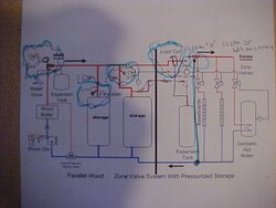
The bubbles are some changes I feel would help

1 A weighted flow check above wood boiler to limit flow when wood pump is off, and the load circ is on trying to draw from storage.
2 flowsetters on the two tanks to determine and adjust the amount of gpm going to them. A ball valve would work and use your hand to "adjust by feel:)
3 Add a good air removal device, like a Caleffi Discal just before the load circ
4 connect the expansion tank(s) at the bottom of that air removal device, along with the fill valve and appropiate backflow device
5 add a properly sized PAB (pressure activated bypass valve) downstream of the load circ, tied into the return. Include a ball valve to aid purging
6 Install a Webstone ball/ purge valve just before the boiler protection valve. With this one valve you could purge each loop one by one via the manual operation of zone valves
7 It might be nice to have a means to take the storage out of the loop and feed the boiler directly to the loads, unless you can assure the correct flow to the loads under the various conditions

hr
 

Attachments

  • MVC-007F.JPG
    MVC-007F.JPG
    39.9 KB · Views: 370
Couple of thoughts / issues:

With the two storage tanks in parallel, there's no particular reason for them to charge evenly. Depending how they're plumbed, they might equalize via thermosiphoning once there's no circulators running, but you might not get predictable performance or maximum stratification. Any reason not to put the storage tanks in series?

In my design, I took care to make the orientation of tees above and below storage so that flow through the zone loop is favored. That's because there's nothing other than the forward flow resistance of the wood circulator's check valve to prevent the load circulator from drawing water through the boiler loop even when the boiler is inactive. It's also important to plumb the storage with large diameter pipe for two reasons:

1) It's critical to reduce flow velocity into storage to minimize turbulence and mixing.

2) It's critical to have an extremely low pressure drop through the storage tank.

The two circs in series issue is not an issue. You wouldn't get double flow in any event, and the pressure drop between the tees at the top and bottom of storage should be virtually zero. Think of it this way: As long as that pressure drop is near zero AND the tees are oriented to favor a loop through storage and the zones, then it's equivalent to having two ports on the top and bottom of storage: one pair for the boiler loop and one pair for the load loop. In that case with both circs running, you'd get flow from the boiler into the top of the tank and right back out again as the load circ draws what it needs. No increased secondary flow, and you wouldn't think of it as two pumps in series. Good observation, though. I should make that plumbing detail more clear in my sticky.

The boiler circ should flow more than the zone circ, assuming that the boiler can produce more heat than the zones can use. You'd probably get that effect even if they're the same circulator model, because the zone loops will almost certainly provide more flow resistance than the boiler / storage loop. If the boiler circ is flowing more than the zone circ, then a portion of the boiler output will flow to storage. During startup and burnout, the boiler may effectively flow less because of input temperature protection, During those times, the load circ will draw a portion of its flow from storage.

Hope this helps.
 
thanks for the kind input, there is plenty of time to make changes and do this right because it wont be started until this summer. i havent even put in my baseboard yet. thats why i cant say anything about pump size or whats going on in the house. i do plan to run 5 zones though. 1-upstairs,2-downstairs,3-basement,4-DHW, and 5-pool in the summer time.
i plan to have this all done for next winter so no need to feel rushed (yet).

Any reason not to put the storage tanks in series?

no reason at all. im torn between 2 tanks similar to the PIC or a 1,000LP tank. whichever i can obtain cheaper. i plan on the 2 tanks because they will fit in the shed without trouble. the LP tank may need an addition to the shed which means concrete..ETC...ETC...

1) It’s critical to reduce flow velocity into storage to minimize turbulence and mixing

i plan to run 1'1/4 black pipe in the shed.
will this work?

The two circs in series issue is not an issue. You wouldn’t get double flow in any event, and the pressure drop between the tees at the top and bottom of storage should be virtually zero. Think of it this way: As long as that pressure drop is near zero AND the tees are oriented to favor a loop through storage and the zones, then it’s equivalent to having two ports on the top and bottom of storage: one pair for the boiler loop and one pair for the load loop. In that case with both circs running, you’d get flow from the boiler into the top of the tank and right back out again as the load circ draws what it needs. No increased secondary flow, and you wouldn’t think of it as two pumps in series. Good observation, though. I should make that plumbing detail more clear in my sticky.

i think i understand? make 1 pipe draw from the main line and split into the 2 storage tanks?


i will make changes to the design and report back.

thanks again!
 
Status
Not open for further replies.