EKO Piping Layout - Anything Wrong with This?

  • Active since 1995, Hearth.com is THE place on the internet for free information and advice about wood stoves, pellet stoves and other energy saving equipment.

    We strive to provide opinions, articles, discussions and history related to Hearth Products and in a more general sense, energy issues.

    We promote the EFFICIENT, RESPONSIBLE, CLEAN and SAFE use of all fuels, whether renewable or fossil.
Status
Not open for further replies.

rickh1001

New Member
Jun 4, 2008
126
upstate NY
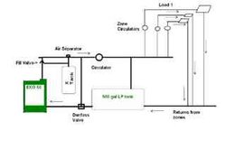
Here is the general layout I am planning for the EKO 60 with a single 500 gal LP tank. The Danfoss valve contains a thermostat, and controls the return water temp. The zones will each have their own circulator. If the EKO is out of wood, it will draw from the storage tank, since the 3-way valve will be closed, preventing circulation through the boiler. Upon startup, the zones will get hot water quickly, as they will draw from the supply line rather than the hot water going into the tank.

I haven't included all the details, but I was wondering if there was anything obviously wrong with this setup that I am missing?

(I have never loaded a figure before, so if it doesn't work, I'll have to find one of the kids to help me!)
 

Attachments

  • EKO_LayoutXP1.JPG
    EKO_LayoutXP1.JPG
    4.2 KB · Views: 578
WoodNotOil,

You are asking the impossible of my pea-sized brain. I barely figured out how to get Paint to work! Using a thousand words instead of a picture though, the layout shows the supply side of the EKO going to an air-separator with expansion tank. The fill valve will also connect there. I haven't shown details of the pressure-relief valve or boiler drain.

After this, is the primary circulator pump, going over to the storage tank and the zones. Between the expansion tank and the primary circulator pump is a T going back down to the Danfoss thermal control valve down on the return line. The zones are taken off the dead-ended supply piping.

I'll try to bribe the kids to help me do a better figure, but hopefully there is enough detail visible to get a general feel for the major components and their layout.
 
just wondering what you are using fror pipe and what size are your lines?? i have the same exact boiler to install so i also need some advice. my eko will be put in a adition on the back of the garage andf piped to the oil boiler in the cellar. thanks
 
I think the Danfoss will be closed in the wrong way for your purposes when cold (open connection from yop to left side in your schematic). In any event, it appears that you would drawing from the bottom of the storage, which is guaranteed to be the coldest water. I also don't see how you avoid pumping nearly 100% of your water through the storage tank when the EKO is operating.

I don't think it's possible to use storage effectively without at least adding a circulator to the system. See the 'simple pressurized storage' sticky at the top. In your case, just erase the oil boiler and associated controls.
 
I think the circ in your case should be on the return line after the Danfoss not on the feed line. I agree with nofossil that you should use the design in his sticky excluding the oil boiler. It should work well for your situation.
 
Status
Not open for further replies.