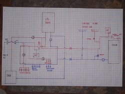
There is a simple solution to your problem. Firstly, the circ on the lpg return line is strangly redundant, there are circs to supply your dhw, radiant, and baseboards, so I fail to understand the purpose of a circ on the return line. If you eliminate that circ and tie the Eko return between the dhw return and the lpg, you will have what could be called a reverse flow parallel hookup. This means that if no zones (including dhw) is calling for heat, then the flow reverses through the lpg keeping it up to temp and ready to take over if the need arises. The water will flow through it and then out to the Eko on the return line.
Some on here will rightfully argue that heating one boiler with another is inefficient, but the upside of keeping a fossil boiler warm is that it can keep the gaskets etc. from the stress of going from stone cold to full temp every so often. I keep my oil boiler hot with my Tarm and simply created a polyiso jacket to increase the insulation around the boiler.
Lastly, yes baseboards are okay for overheat, so long as they are above the boiler. Size them to output around 10% of the btu rating of your boiler. I hope that helps.
Edit: You may even be able to do what I suggested above without having to take out the circ on the lpg return, but I am curious what it is for. Also, you may want to look at the sticky "Simplest Pressurized Storage System Design" which shows a type of parallel hookup that does not heat the second boiler. In your case you would just ignore the piping for the storage. See if you can make that work with your existing piping and then you would have the possibility of adding storage later using that design. Just a thought.