EKO40 Propsed System Layout

  • Active since 1995, Hearth.com is THE place on the internet for free information and advice about wood stoves, pellet stoves and other energy saving equipment.

    We strive to provide opinions, articles, discussions and history related to Hearth Products and in a more general sense, energy issues.

    We promote the EFFICIENT, RESPONSIBLE, CLEAN and SAFE use of all fuels, whether renewable or fossil.
Status
Not open for further replies.

Northwoodsman

New Member
May 21, 2008
99
Northern MI
Guys,

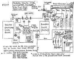
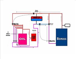
Attached is my proposed system layout for my new EKO40 I am picking up in a few weeks. Please take a look at the detailed layout and let me know what changes should be made (and why).

I have had the Burnham boiler, (2) zones of radiant floor heat (using the Heat Link brand Stat Link controller and zone valves) and (1) zone of baseboard heat in operation for approx. 6 years and it works great!!!!

I plan to control the entire system with an AB (Allen Bradley) Micrologix 1500 PLC which has (4) analog inputs and (2) analog outputs (both are 0-20 mA) along with many digital I/O.

However, I am not quite sure of the best location/what type/brand to use for my 4-20mA temp sensors. Does anyone have experience with a specific brand of temp sensor that are reasonable priced and of good quality. Also, where would be the best location to put these and exactly how many would be required to best/most efficiently control the entire system (I can add additional sensors/analog cards if needed).

I look forward to getting your feedback and will share my results of the system (once it's up and running) with anyone who is interested.

Thanks,

BC
 

Attachments

  • EKO40 layout1.jpg
    EKO40 layout1.jpg
    73.2 KB · Views: 1,138
Interesting approach. I have no experience with the AB controller or with any temp sensors that provide the 4-20ma signal that the controller wants. I do know that some thermocouple signal conditioners can provide that output.

I'm confused by the Taco 010IFC above the storage, and the army of zone valves around it. If you eliminate them, you almost have my 'simplest pressurized storage' approach. The Taco 007 would guarantee that you's have flow through the zones whenever you needed it.

Does the Burnham have its own circulator that's not shown?
 
Thanks for the reply,

Regarding the zone valves around the 010IFC circ. pump, they will be used to control who is heating who.

For example, if A & B are open and C,D,E are closed, then the EKO40 will supply the heat to the house and other loads.
If E is open and A,B,C,D are closed, then the Burnham boiler will heat the house and other loads.
If A and C are open and B, D, E are closed, then the EKO40 will heat the 1,000 gallons of storage water.
If B and D are open and A, C, E are closed, then the 1,000 gallons of storage water will heat the house.

By using a PLC that I already have (I also have an electrical enclosure, power supply and many Ice Cube relay's) I will not need to buy a proprietary controller to control the many zone valves. In addition, I can create a legend plate on the face of the enclosure that will have the entire system (via. light bulbs) on display so I can see exactly what is going on (i.e. pumps on/off, valves on/off, different temps displayed etc.). Also, I will be able to store the different temps that I record and can use these to help with making the most efficient system.

I know this may be a little bit of an overkill but one cannot deny that it will give me the most efficient control of the system and also will be very helpful for troubleshooting.

I've studied your website quite a bit and like what you have going on. However, I do not have your background with electronics and thus took a little different hardware approach. As you can see, I am doing Radiant floor heat wherever I can due to the fact that it will be somewhat efficient at 120 degree F and thus with 1,000 gallons of water strored at approx. 180 degree F (60 degree F delta) this gives me approx. 450,000 BTU potential heat. Based on my anticipated heat losses, exact heatloads on the system at any given time and the ambient temp, this will give me a 10-15 hour heat supply to my house and misc. heat loads.

Regarding your question about the Burnham boiler having its own circ. pump, yes it does. In my diagram it would be circ pump #2. What I forgot to show is that there is a circ. pump for the baseboard zones and it is located after the baseboard zones "T" off of the main supply run and before BBZV1 (baseboard zone valve 1).

The (2) main pumps for the EKO 40 are Taco 010IFC, three speed pumps. I did this because I plan to fire the EKO 40 on a weekly basis (approx.) during the summer and was thinking that I could use a slower speed setting (less amp draw) on the 010's since I will not be having any other heat loads except the DHW. Additionally, I plan to add several soalr collectors next year and this would additionally reduce the heat load that the EKO would need to supply.

Finally, I am thinking about putting in some bypass valves (to bypass the Army of zone valves) that would let me run the system in case my PLC was stopped working (it wouldn't be quite as efficient but would let me heat my house with wood non the less). Also, would you recommend installing a high temp Aqua stat at the supply line coming from the EKO 40?

Thanks and Waiting for Feedback !!!!

BC


nofossil said:
Interesting approach. I have no experience with the AB controller or with any temp sensors that provide the 4-20ma signal that the controller wants. I do know that some thermocouple signal conditioners can provide that output.

I'm confused by the Taco 010IFC above the storage, and the army of zone valves around it. If you eliminate them, you almost have my 'simplest pressurized storage' approach. The Taco 007 would guarantee that you's have flow through the zones whenever you needed it.

Does the Burnham have its own circulator that's not shown?
 
Radiant is good for the reasons that you mention. I can't quite make out your schematic in the radiant loop section, but I assume that you have a circulator and adjustable mixing valve there to provide water at a set temperature for the radiant.

You'll need a check valve to prevent backwards circulation through the Burnham when you're running off storage.

The size / speed of the EKO circulator should be based on the EKO's output, not on the load. If you need 15gpm to carry heat away from the EKO, that's what you want to size the pump for. If the loads only need 4gpm, then your load pump(s) can be smaller. In my suggested schematic, the extra flow in this case would go through storage. Note that in my actual system, my approach is closer to what you're doing - pumps and valves that are either on or off depending on system mode.

Would it make things simpler and cleaner to move the Burnham circ to the inlet of the burnham? It's redundant during EKO or storage operation if there's a baseboard circ and a radiant circ.
 
Yes, I do have a circulator and adjustable mixing valve (which is tied into my Stat Link controller-it uses water temp and ambient temp to select the best temp to put the water at).

Regarding the check valve on the Burnham, since it has a zone valve (E) do I still need a check valve (this seems redundant).

Regarding the redundant circs at the baseboard and radiant zones, these are already 100% installed and operating and it would be a hassle to move one of them. Does it hurt the performance/operation of the system by having both of them or are you just recommending it be moved to "clean up " the system?

Finally, where would you recommend installing the thermocouples at to get the most accurate monitoring of system temps. and corresponding most efficient operation of the system? I'm thinking that I should install them at:
1.) Supply outlet of EKO 40 and top of upper storage tank (I would use these two temps to switch on the proper heat source i.e. EKO40, tank or Burnham).
2.) Return inlet at EKO 40 and bottom of tank (I would use these two temps for reference only-they could be used to monitor the effect/efficiency of any changes I make to the system in the future).
3.) I would have a future thermocouple on my solar collectors.

Lastly, what do you think about putting by-pass valves around the zone valves (including a check valve at the Burnham) so that I could run the system in the "simple pressurized mode" as you mentioned previously. As I see it, this would require 1 valve to by-pass the the 2 zone valves on my supply run (A & B), 1 valve to by-pass the 2 zone valves coming from my storage tanks (C & D) and one valve to by-pass the zone valve (E) at the Burnham (this would also include the installation of a check valve at this location).

Thanks again !!!!

BC


nofossil said:
Radiant is good for the reasons that you mention. I can't quite make out your schematic in the radiant loop section, but I assume that you have a circulator and adjustable mixing valve there to provide water at a set temperature for the radiant.

You'll need a check valve to prevent backwards circulation through the Burnham when you're running off storage.

The size / speed of the EKO circulator should be based on the EKO's output, not on the load. If you need 15gpm to carry heat away from the EKO, that's what you want to size the pump for. If the loads only need 4gpm, then your load pump(s) can be smaller. In my suggested schematic, the extra flow in this case would go through storage. Note that in my actual system, my approach is closer to what you're doing - pumps and valves that are either on or off depending on system mode.

Would it make things simpler and cleaner to move the Burnham circ to the inlet of the burnham? It's redundant during EKO or storage operation if there's a baseboard circ and a radiant circ.
 
My question was about moving the Burnham circ, not the baseboard circs.

I couldn't see the zone valve on the outlet of the Burnham.

You need to make sure that any zone valves that are in the main flow path from any heat source have a large orifice. Most zone valves have a very small orifice to help balance flow when you have several parallel zones open. In the case of the Burnham, using a circulator with an integral flow check at the location of one valve E or at the Burnham inlet would accomplish the same thing without the flow restriction issues.

I agree with inlet and outlet of EKO for temp sensors, as well as top and bottom of storage.

I also have thermocouples in the EKO secondary combustion chamber and flue, as well as a sensor for solar output, middle of storage, and DHW (I have that one in the aquastat well).

By the way - I've been whining about the readability of your schematic. Line drawings are MUCH more legible if they're saved as .gif rather than .jpg files. The JPEG compression algorithm fails badly with sharp transitions - it's much better suited to photographs.
 
You can prob. eliminate 2) z. valves by using 2) 3-way z.v (taco) ;1) on each side of the 0010
You don't really need a z.v. @ the gas boiler, if you have a flow control & it is piped properly...
my 2 cents


N.H. Master plumber & P&H;shop owner since 1987
 
I have attached a more clear system drawing and have eliminated zone valve E and replaced it with the circ. pump as nofo mentioned peviously (it makes much more sense to move this circ. pump to this location as it eliminates a zone valve and provides for less restriction in flow).

Regarding the use of 3 way valves vs. the army of single zone valves sounds like a great idea. I went on line and downloaded the Taco Heat Motor Zone Valve Catalog.

However, it looks like they don't offer this style zone valve for use with 1-1/4" copper. They list a 562 which is a 3 way (sweat) valve for 1" copper but only the 573 2 way valve for 1-1/4" copper.

I would really like to stay with the 1-1/4" copper as it reduces the friction when the water is flowing (My EKO40 requires approx 13.6 GPM for full/proper heat removal).

Please let me know if you know of another 3 way Taco zone valve that is available for 1-1/4" copper.

Thanks,

BC


babalugatz said:
You can prob. eliminate 2) z. valves by using 2) 3-way z.v (taco) ;1) on each side of the 0010
You don't really need a z.v. @ the gas boiler, if you have a flow control & it is piped properly...
my 2 cents


N.H. Master plumber & P&H;shop owner since 1987
 

Attachments

  • EKO40 Layout.gif
    EKO40 Layout.gif
    30.9 KB · Views: 651
Let's try that again, I don't want anyone getting a stiff neck trying to read my schematic-sorry !!!!

Thanks again,

BC

Northwoodsman said:
I have attached a more clear system drawing and have eliminated zone valve E and replaced it with the circ. pump as nofo mentioned peviously (it makes much more sense to move this circ. pump to this location as it eliminates a zone valve and provides for less restriction in flow).

Regarding the use of 3 way valves vs. the army of single zone valves sounds like a great idea. I went on line and downloaded the Taco Heat Motor Zone Valve Catalog.

However, it looks like they don't offer this style zone valve for use with 1-1/4" copper. They list a 562 which is a 3 way (sweat) valve for 1" copper but only the 573 2 way valve for 1-1/4" copper.

I would really like to stay with the 1-1/4" copper as it reduces the friction when the water is flowing (My EKO40 requires approx 13.6 GPM for full/proper heat removal).

Please let me know if you know of another 3 way Taco zone valve that is available for 1-1/4" copper.

Thanks,

BC


babalugatz said:
You can prob. eliminate 2) z. valves by using 2) 3-way z.v (taco) ;1) on each side of the 0010
You don't really need a z.v. @ the gas boiler, if you have a flow control & it is piped properly...
my 2 cents


N.H. Master plumber & P&H;shop owner since 1987
 

Attachments

  • EKO40 Layout.gif
    EKO40 Layout.gif
    43.1 KB · Views: 747
Thanks for the new schematic - much easier for my ancient eyeballs.

I'd love some input from real plumbing guys on this question:

What would happen if you simply removed the circulator and the four zone valves above the storage?

My take is that the system would work fine. If the collective flow of the baseboard and radiant circs is less than the EKO circ, then some percentage of the EKO output would go to storage - I think that's exactly what you would want.

The only wrinkles that I can see is that you'd need a check valve where the 'B' zone valve is to prevent the Burnham from circulating through storage, and you might need spring loaded check valves on the output of both the EKO and the Burnham to ensure that the zones draw only from storage when the boilers are inactive.

The Taco 573 is an expensive zone valve, and while it has a Cv of 7.2, a pair of them in series is still a lot of flow restriction for a primary flow path.

Any thoughts from the pros?

By the way - I'd be tempted to look at building a giant multi-tube sidearm with a PVC outer shell for the solar panels. Use the internal copper to carry the pressurized boiler water. Just a thought....
 
Nofo,

I've thought about your idea of removing the 010 circ and (4) zone valves from the top of the upper tank and have the following comments/questions:

1.) I agree that a check valve (I'm assuming a flapper type) is needed at Zone Valve B location to prevent Burnham from going back to storage or EKO.
2.) I'm not quite sure what you mean by a "spring loaded" check valve on the output of the EKO and Burnham to ensure that the baseboard/radiant circ's draw only from storage.
If a spring loaded check valve is placed at these 2 locations to prevent the the unwanted drawing of water from the EKO or Burnham wouldn't it also prevent the EKO and Burnham from pumping heated water into the main supply line (it seems like the pump pressure from the boilers would close the check valve and prevent flow altogether)? Maybe this is a special type of check valve that I am not famiiar with or the spring pressure can be adjusted for different pressures-please educate me on this.

Other than my question in 2.) (I'm thinking a zone valve vs. check valve at each location is required and thus this would reduce the # of zone valve from 5 to 2) I think this sounds like a great idea (I've noticed that you're always looking to simplify things/thinking out of the "BOX"-which is a GOOD THING).

Regarding the giant heat PVC HX, I was planning on making one of these for the hot tub water (I was told by someone who made a 6" dia. PVC shell with copper tube (pressure) (3 ft. long x 6 runs) HX that it works just fine. I suppose I could SUPER SIZE this HX for the solar collectors. In addition, why couldn't I make the same type of heat exchanger for my DHW?

Finally, any hints of where to go for help in building my own solar collectors?

Let's wait for the PRO'S to evaluate your suggestion of removing the zone valves and (1) circ pump.

Thanks again !!!!

BC


nofossil said:
Thanks for the new schematic - much easier for my ancient eyeballs.

I'd love some input from real plumbing guys on this question:

What would happen if you simply removed the circulator and the four zone valves above the storage?

My take is that the system would work fine. If the collective flow of the baseboard and radiant circs is less than the EKO circ, then some percentage of the EKO output would go to storage - I think that's exactly what you would want.

The only wrinkles that I can see is that you'd need a check valve where the 'B' zone valve is to prevent the Burnham from circulating through storage, and you might need spring loaded check valves on the output of both the EKO and the Burnham to ensure that the zones draw only from storage when the boilers are inactive.

The Taco 573 is an expensive zone valve, and while it has a Cv of 7.2, a pair of them in series is still a lot of flow restriction for a primary flow path.

Any thoughts from the pros?

By the way - I'd be tempted to look at building a giant multi-tube sidearm with a PVC outer shell for the solar panels. Use the internal copper to carry the pressurized boiler water. Just a thought....
 
I'd hesitate to use a PVC HX for DHW because the pressure is MUCH higher than for a solar system. PVC loses strength at temperature over time. Maybe someone who actually knows will chime in, but it makes me nervous.

The check valves that I refer to would be installed to allow flow in the desired direction, not backwards. Spring loaded means that they allow no flow until a certain pressure is reached - typically around 1 PSI. The whole purpose is to make sure that the zone and radiant circs draw through storage rather than through the cold boilers. Plumbing the tees into and out of storage in the correct orientation could also increase the flow preference for storage vs. through the boilers. Zone valves would be guaranteed to work, but they impose more flow restriction (I think) and require additional controls.

I too am hoping for words from the pros.
 
nofo,

Just to confirm, when the basebaord or radiant circ's are pulling hot water from the storage tanks this pressure is less than the spring pressure on the check valve at the Burnham and EKO and thus these checks remaim closed(the water is taking the path of least resistance). However, when the Burnham or EKO is pumping hot water to the main supply run they will overcome this spring pressure easily and open up fully.

I would agree that this system design should accomplish the same objectives as my original proposal using the (5) zone valves.

Thanks for your help and we'll have to wait and see what the PRO's think about it.

BC


nofossil said:
I'd hesitate to use a PVC HX for DHW because the pressure is MUCH higher than for a solar system. PVC loses strength at temperature over time. Maybe someone who actually knows will chime in, but it makes me nervous.

The check valves that I refer to would be installed to allow flow in the desired direction, not backwards. Spring loaded means that they allow no flow until a certain pressure is reached - typically around 1 PSI. The whole purpose is to make sure that the zone and radiant circs draw through storage rather than through the cold boilers. Plumbing the tees into and out of storage in the correct orientation could also increase the flow preference for storage vs. through the boilers. Zone valves would be guaranteed to work, but they impose more flow restriction (I think) and require additional controls.

I too am hoping for words from the pros.
 
nofo,

I've attached a simplied system drawing showing the things we've discussed and also have a few questions as shown on the schematic (are adjustable spring pressure check valves avail)?

Thanks again

BC

nofossil said:
You have my idea exactly. This depends in part on using large diameter / low restriction plumbing through the storage loop.
 

Attachments

  • StorageTankSchematic.gif
    StorageTankSchematic.gif
    30.5 KB · Views: 599
Like you, my concern was charging the tank with out pulling water from the boiler. Or pulling water from the biomass if it was cold instead of the tank.

My solution was,

1) Connecting a zone valve and will only open when wood circulator is on, It will charge the tank and the main circulator zone value will act as a stop.

2) The main circulator and main zone valve will only come on when boiler zones engage , it will pull water from the biomass or tank depending if the wood zone valve is open or closed.
 

Attachments

  • Publication16.jpg
    Publication16.jpg
    56.4 KB · Views: 584
Northwoodsman said:
nofo,

I've attached a simplied system drawing showing the things we've discussed and also have a few questions as shown on the schematic (are adjustable spring pressure check valves avail)?

Thanks again

BC

nofossil said:
You have my idea exactly. This depends in part on using large diameter / low restriction plumbing through the storage loop.


hey, nobody asked me but:
don't ever use 'swing' checks horizontally....use 'flow' checks ; big dif. is...ghost flow can occur w/ swing type valves, flow-checks have a weighted brass cylinder that slides up vertically when a pump pushes water through it, and the weight of it keeps it down & off unless a pump is directly forcing it open.
 
oh, and on your storage tank loop; you'll need a dedicated pump for that
 
babalugatz said:
oh, and on your storage tank loop; you'll need a dedicated pump for that

Why wouldn't the zone circs do the job? If he has the check valves as discussed and has a very low head path through storage, they should draw from storage just fine.

I don't know of adjustable spring check valves, but I think any of the ones I've seen would offer more than enough cracking pressure to ensure that all from is through storage. Absolute worst case is that you'd have to add a zone valve to absolutely prevent ghost flow if the zone circs are way more energetic than I expect.
 
Status
Not open for further replies.