Englander cleaning and heat exchanger design

  • Active since 1995, Hearth.com is THE place on the internet for free information and advice about wood stoves, pellet stoves and other energy saving equipment.

    We strive to provide opinions, articles, discussions and history related to Hearth Products and in a more general sense, energy issues.

    We promote the EFFICIENT, RESPONSIBLE, CLEAN and SAFE use of all fuels, whether renewable or fossil.
Status
Not open for further replies.

donbryce

Member
Jan 8, 2009
110
NB Canada
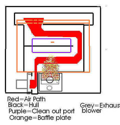
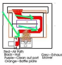
I hope this doesn't sound too anal, but I was wondering if anyone has attempted to draw the internal panels and passageways comprising the heat exchanger/exhaust gas path for the Englander 25-PDVC and/or 25-PDV? I've tried to examine this on my PDVC with a light and mirror, with the baffle plate removed, but it still bugs me that I'm not sure exactely where to shove a small diameter hose into the non-visible openings at the top behind this plate for best cleaning. Anyone care to share their knowledge on best cleaning technique with a vacuum? And yeah, I'm aware of the leaf-blower method, but for those of us who want to do the vacuuming, it would be nice to know what works and what's a waste of time.

I asked in another thread if Mike Holton could provide same, or even better, a picture of the stove's internals during manufacture, before the box is welded up. I tried but couldn't find that thread, so maybe he will chime in and help us out.
 
Mike very kindly sent this drawing along. Thanks. I think that the only part of the chamber that can't easily be vacuumed would be at the very bottom of the passageway, below the visible shelf in the clean out port. I now would try snaking the hose down through the opening at the far right of the cleanout port, where the shelf ends, and try to push it toward the blower, or down through the opening under the visible shelf.
 

Attachments

  • 25PDVC airpath drawing02.jpg
    25PDVC airpath drawing02.jpg
    22.9 KB · Views: 1,697
donbryce said:
Mike very kindly sent this drawing along. Thanks. I think that the only part of the chamber that can't easily be vacuumed would be at the very bottom of the passageway, below the visible shelf in the clean out port. I now would try snaking the hose down through the opening at the far right of the cleanout port, where the shelf ends, and try to push it toward the blower.

Is that for the 25 or the 25-c?
 
i gotta tell ya, the drawing don posted was a "quickie" i did up in paint, i guess if its helpful for our members im happy he posted it , though i wouldnt call it "detailed" thanks for editing it don as i didnt do the color chart happy it is up where it can be a help.
 
Deffy said:
thats great, always wanted to know that. i kind of assumed that was the path but good to know for sure.

one question, this drawing shows the baffle plate covering the entire cleanout port. my cleanout port is wider than the baffle plate by about 1.5 inches on each side.

wont the stove exhaust bypass half the route in my case and go right down the cleanout port?


you sure about that? the baffle should cover the whole cleanout port the port is 8 1/4 wide, the baffle should be 12 5/8 wide

as for the air path for the 25-pdv , the same basic route is followed although its a larger air exchange area in that unit with more steel exposed to the convection housing. and the cleanout is different (smaller) the different baffle setup required the smaller cleanout as too much air would bypass it if bigger.
 
I was wondering the same thing. What does the heat exchanger path of the 10-CPM look like?
 
I take a clear plastic hose and attach it to my vac and stick it down in openings for super clean out,
 

Attachments

  • 25PDVC airpath drawing02.jpg
    25PDVC airpath drawing02.jpg
    13.3 KB · Views: 1,258
Status
Not open for further replies.