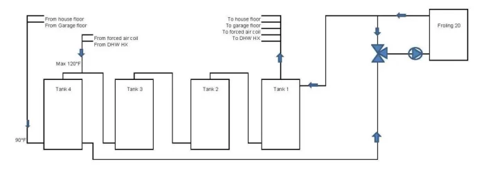
Froling 20 return water control with 0-10v mixing valve

  • Active since 1995, Hearth.com is THE place on the internet for free information and advice about wood stoves, pellet stoves and other energy saving equipment.

    We strive to provide opinions, articles, discussions and history related to Hearth Products and in a more general sense, energy issues.

    We promote the EFFICIENT, RESPONSIBLE, CLEAN and SAFE use of all fuels, whether renewable or fossil.
Status
Not open for further replies.

Beagle Dad

Member
Sep 17, 2014
46
Ottawa Ontario
My Froling 20 installation includes a 0-10volt mixing valve to control the water temperature entering the boiler. The valve is controlled using a Vesta controller which provides the required 0-10v signal to modulate the valve to maintain the return water setpoint. The setpoint is varied to provide normal or extended burn times. The boiler controls when the boiler circ pump starts and stops.

I use an Erie valve with a CV of 8.0. This CV was selected since the flow through the boiler is 7 USGPM. This flow rate was selected since a 20°F temperature rise on a boiler output for 70,000 BTH gives 7 GPM.

My 3-way valve is Erie VM3427P33A000, 1" 3-Way NPT Proportional Non-Spring Return Zone Valve, 8 CV (24V) another valve option is Belimo B322B TR24-SR
 

Attachments

  • Flow through valve.pdf
    139.6 KB · Views: 201
  • Froling 20 with mixing valve 1.pdf
    99.4 KB · Views: 204
  • Pump view.pdf
    130.3 KB · Views: 160
  • Supply view.pdf
    97 KB · Views: 217
Will be studying... Thanks.
This would also provide boiler protection...nothing else required?
I like the concept of controlling return temp and then letting the boiler do its thing.

I have been thinking that for me, there is no rush to charge the buffer tank, so why not modulate down to 30%. Modulating down boiler when hot enough buffer water is available would also seem to extend run time. I have to think about this...

Edit: Would you have a piping diagram that you could share?
 
Second on huggdawg request, also would be interesting to see a plumbing schematic of your system. I'm not sure that the Froling literally modulates down as you suggest. I know it has a degree of control over the draft fan speed, which would affect output, but to actually obtain full modulation I think it also would have to control the volume of water moved through the Froling by the loading circulator. The typical loading unit, which you do not appear to have based on your pictures, does not do this is as it has a fixed circulator speed. Versions of the Froling available in Europe may have this additional modulation control.

It seems to me that the ideal would be to have a draft fan speed which maintains the optimum burn rate and then a modulated circulator to maintain the optimum volume of water moving through the Froling to handle the optimum btuh output.
 
I think Beagle Dad stated in another thread that his Froling wood boiler can modulate down to 50% and still maintain clean operation.
 
I'm doubting this. I know the Froling deep programming can set the boiler to operate at outputs less than rated maximum. For example, the FHG-L50 (170,000 btu) can be set to emulate 140,000 and 120,000 btuh outputs, if I remember correctly. But woodboilers.com has advised that this is not implemented without a variable speed circulator/loading unit and these are not available in the US market.
 
Second on huggdawg request, also would be interesting to see a plumbing schematic of your system. I'm not sure that the Froling literally modulates down as you suggest. I know it has a degree of control over the draft fan speed, which would affect output, but to actually obtain full modulation I think it also would have to control the volume of water moved through the Froling by the loading circulator. The typical loading unit, which you do not appear to have based on your pictures, does not do this is as it has a fixed circulator speed. Versions of the Froling available in Europe may have this additional modulation control.

It seems to me that the ideal would be to have a draft fan speed which maintains the optimum burn rate and then a modulated circulator to maintain the optimum volume of water moving through the Froling to handle the optimum btuh output.


I selected the Froling boiler for its ability to modulate the firing rate to control to the Supply water setpoint. The boiler achieves the variable output by varing the fan speed and the primary air. The secondary air is varied to maintain a 8% O2 in the flue. The fan on the Froling 20 has a factory setup for the Fan to vary between 35% to 85% speed.

My system was designed with a constant flow through the boiler of 7 GPM and to vary the return water to the boiler to create the reduced load condion.

Boiler ouput = 500 * °F temp rise * Flow in GPM

Froling 20 output of 70,000 BTH = 500 * 20 * 7

The boiler has a stated ouput range of 35,000 to 70,000 BTH. The low end is only possible when the fire box is loaded to less than 50% on a bed of coals, otherwise you will get smoke when the new wood off gases.

My return water control targets a 14°F temperature rise 2.5 hours after the boiler is fully loaded.

The storage for the system consists of 4 tanks connected in series to maximize storage. Each tank is 7.5 feet tall for an effect height of 30 feet. The boiler is connected to the tanks with dedicated connections independent from the heating loads. With the high amount of stratification in the tanks and the cool return water from the radiant floor loads the flow rate from the tanks to the boiler is about 2 GPM until the bottom of tank 4 starts to heat up at which point the flow will increase to 7 GPM. This starts to happen from 80% tank capacity.


Layout (2).jpg
 
  • Like
Reactions: velvetfoot
I'm a bit curious as well. I'm assuming it's a PID rule by your description.

As a side note, each Vesta analog output has two output signals: 0-5V and 0-20mA. If you're clever, you can select a load resistor and connect it to the 0-20mA output to get an output voltage range on that pin of 0-12V (or even 0-18V if you have an 18V power supply).

I used the 4-20 mA output with a 500ohm resistor to get the 10volts
 
  • Like
Reactions: TCaldwell
Mixing valve rules

View attachment 170584

View attachment 170585

Boiler Cold is set to ON when the boiler is below 145°F
Long Burn is set manually to reduce boiler output slightly, no smoke will be produced when fire box is filled.
Extended Burn is set manually when a longer overnight burn is required. Full load of wood is used.

Four different return water setpoints are used.
  1. 150°F when the boiler is heating up from cold

  2. 152°F when the boiler is at temperature, givesfull firing rate

  3. 155°F longer burn

  4. 158°F extended burn
The boiler setpoint in the Froling is 172°F and the high limit setpoint for slumber etc. are at the original 183 and 185°F values. The reason for this is to provide some space between the boiler setpoint and the high limits, using the typcal 180°F is too tight. When the boiler is holding a minimum fire there is a period during the burn when the BTU output can still cause the SWT to over shoot the setpoint

The majority of the rules shown above are to keep the heat in the boiler once the fire has started to burn out. The idea is the keep the boiler hot by closing the mixing valve rather than keeping it open which would start to bring heat back from the tanks to the boiler. I look at Tank 1 and Tank 2 and compare these temperatures to what the boiler is sending out then raise the RWT setpoint to close the valve as the boiler cools.

Here are a couple of screen shots from yesterday.

upload_2016-1-1_9-11-15.png


The boiler heats up, when the blue line reaches the pump start temp the boiler starts the pump. The mixing valve comes under control and the tanks start to heat up.

upload_2016-1-1_9-14-51.png


At about 9:30 PM the boiler was filled and the Extended burn was set to ON, At about Mid night the Return water setpoint increased to 158 for the balance of the burn. The fire is out now since it is not very cold here only 25°F over night.

upload_2016-1-1_9-20-16.png


My outdoor air sensor is not connected
 
  • Like
Reactions: velvetfoot
Here are the missing screen shots
upload_2016-1-1_9-31-12.png


PID rule

upload_2016-1-1_9-33-39.png
 
In lieu of the Vesta, could that Erie valve be controlled by something like this?:
http://www.supplyhouse.com/Honeywel...er-w-2-Temp-Inputs-2-Analog-Outputs-2-Sensors
Pretty sure that would work, and way cheaper than a Vesta. Nice thing with Vesta (if you have one) is that you can tweak settings easily or even change setpoints dynamically, and then review the datalogs to see exactly what happened.

There have been *many* cases where we've gone in and replaced a bunch of discrete controls just to get everything working together better. I replaced my boiler control years ago so that I could change the outlet temperature on the fly to match the needs of the heat loads.
 
Thanks.
All those discrete controls can add up as well, even if they do work together. Those hours in the basement looking at temps are getting tedious.
 
Thanks.
All those discrete controls can add up as well, even if they do work together. Those hours in the basement looking at temps are getting tedious.
When I was designing my system I found that the cost of the discrete controls were going to add up and in the end only provide limited functionality. For the cost of the Vesta I was able to do far more control, trending and see the system from any device such as the Desktop, IPad and Smartphone from inside my home network or from away. These features really complete the system.
 
Are there differences in performance, or whatever, when the proportional mixing valve is on the supply side? I saw this in the Siegenthaler NYSERDA presentation:
mix valve on supply.png
 
Are there differences in performance, or whatever, when the proportional mixing valve is on the supply side? I saw this in the Siegenthaler NYSERDA presentation:
View attachment 172395
The 3-way valve located after the boiler will work the same as when the valve is before the boiler. The valve must be suitable as a diverting valve which takes 100% of the follow and diverts it to two possible paths. The Belimo valve is suitable for this application as your picture shows.
 
  • Like
Reactions: velvetfoot
A spring return valve would only go to the fail position on a loss of power. When this occurs the boiler would most likey have lost power as well which would trigger the heat dump and the fire would tapper off with the loss of the induced draft fan. Return water control would not be important at this time.

If the valve lost power only during operation a non spring return valve would be in a position which would keep the minimum return to the boiler at a high enough temperature. The valve modulates between 45 to 60% once the boiler is up to temperature, see post 12 trends above
 
That's true. For my pellet boiler, chances are if it was still low temp and power failed, the temps wouldn't get that high. If it was at high temp, the valve would be open or partially so. I should probably have a dump zone too, or a ups. I guess I could kill the power one day and see what happens. :)
On a side note, I just ordered this:
http://www.ebay.com/itm/Johnson-Con...797954?hash=item3f57ca08c2:g:UhEAAOSw8-tWVNH9
 
Status
Not open for further replies.