Heating system design utilizing potable water

  • Active since 1995, Hearth.com is THE place on the internet for free information and advice about wood stoves, pellet stoves and other energy saving equipment.

    We strive to provide opinions, articles, discussions and history related to Hearth Products and in a more general sense, energy issues.

    We promote the EFFICIENT, RESPONSIBLE, CLEAN and SAFE use of all fuels, whether renewable or fossil.
Status
Not open for further replies.

Shelterman

Member
Feb 18, 2008
41
South Central, MO
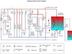
Ok. I'm going to try one more time to to make my current system work with a wood hydronic system.

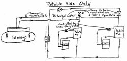
I have an unusual situation in that my existing heating system, while it is hydronic, uses potable hot water as the heating medium (as it also supplies the drinking hot water needs of the house). This system uses what are essentially very high output water heaters (both, 100k btu) in which the potable water is circulated through heating coils in two air handling plenums controlled by two separtate thermostats (in effect two separate zones).

Ideally I would like to keep my current system intact...including the use of potable water.

About a year ago, I asked this same question to those on this forum and was told to use shell and tube heat exchangers. However, I really don't think shell and tube exchangers are practical in this application due to the fact that in order to supply the btu demands of these units, the size and cost of the exchanger would be prohibitive. I suppose I am not too stubborn to be convinced that this is still the way I need to go, but it just doesn't seem right to me.

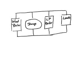
I had recently given up the idea of using potable water in the coils and was given valuable assistance by Eliot who helped me up my system with non-potable water. Although I may still have to go with that method, I thought I would give one more shot at presenting the knowledgeable individuals on this forum with an idea that I have in adapting nofossil's "Simplest Pressurized Storage System Design" to the system that I already have AND also maintain the use of potable water.

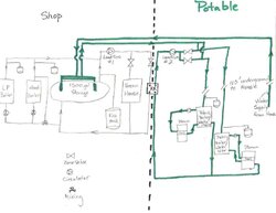
I know in some ways that a non-pressurized storage tank would be better suited to my set up, but I have located a very inexpensive 1500 gallon propane tank that I would really like to use.

A couple of my concerns on this design is the fact that I will have mineral buildup in the flat plate heat exchanger (which will be remedied by regular cleaning) and I am also concerned that a single flat plate and exchanger with 1.25" ports will support the volume of water and BTUs that will need to be pushed through it. Would two exchangers set up in parallel work better?

Please look at the attached design and give me your thoughts.
 

Attachments

  • Hot water diagram.jpg
    Hot water diagram.jpg
    34.2 KB · Views: 1,469
"That schematic doesn’t quite make sense. It looks like the two zone valves are connected together on both sides, for one." The first thing to keep in mind is that everything in green is under domestic water line pressure and is all potable. Being that all the water is potable I'm doing things a bit differently than would normally be done. If you are referring to the two zone valves on the potable side of the diagram, I was trying to illustrate the valves plumbed in parallel. Each zone valve is controlling one of the two the house zones and are downstream of load circulator #2. I've attached revised diagram of the potable side of the proposed system, hopefully making it easier to understand. The original diagram looked a little funny because when drawing it the first time I felt I didn't have enough room to draw the parallel zones as one normally would. The two zone valves in question would regulate the flow of hot water to each respective Polaris unit. When the demand for heat is called by the thermistor or an aquastat, (which would be attached to the Polaris), the corresponding zone valve would be opened, the limit switch would close and the load circulator would be energized.

The circuit on each Polaris going to the plenum heating coil would operate just as it does currently only now would operate as a secondary circuit. The secondary circulator would push the water to the coil when the house thermostat calls for heat, just as it does presently.

"Are those immersed potable HX coils in the storage tank?" Yes they are. The plan is to purchase or construct the linear type drop in DHW coils and plumb them in parallel to preheat the cold, outside replacement water when hot water is pulled from the Polaris' for domestic use, showers, etc. And yes, I do have it plumbed to the supply side of the heating circuit (remember, it is all potable water). In actual practice, I may plumb it with one or two mixing valves as you suggest on your website.

I hope this better explains my idea. In my mind it looks like it would work, however, if it won't I want to be told now so I can go back to plan B...sending non-potable boiler water through the heating coils and using the Polaris' as conventional water heaters. My desire however is to keep all the water in my house potable so I can easily revert back to my original system in the event I need to be away from home for several days.

Again, I don't mind being told that this idea won't work, I just want to make sure that it is thoroughly understood by one of you knowledgeable gentlemen before the idea is ditched.

Thanks again for your help.

David
 

Attachments

  • Heating Diagram (potable side only).jpg
    Heating Diagram (potable side only).jpg
    31.6 KB · Views: 657
Salmonella would worry me.
 
I don't think anyone with a plumbing and/or heating background would ever advise mixing your drinking water pumbling with your heating water. First and foremost, I don't think you'd ever be able to meet code this way. And second, too much risk of contaminating your drinking water in my humble opinion...

Aside for the mixing risks - I don't think your coils and heat exhangers will last particularly long with a constant flow of untreated, highly oxygenated potable water. It'll would be a maintenance nightmare to keep things free and clear...
 
I'll agree that it's unconventional, but as an engineer I'm more interested in technical problems rather than code compliance. We routinely run potable water through copper pipe and heat exchangers - that's what a tankless unit is, after all. I don't know about scale buildup in heat exchangers. It's probably highly dependent on water hardness. I'm currently preheating my potable DHW by running it through an immersed coil in my storage, and tankless heaters are also designed to process potable water. I don't see a technical problem with that part of it.

I'm still bothered by the line that connects below the right zone valve and goes to the left of a tee below the left zone valve. Unless there's something else going on, those two zone valves are in parallel.

I also don't yet understand the four connections to each Polaris. When you're heating from storage, what is the flow through (or around) the Polaris units, and how do you keep them from firing? Most tankless units fire based on flow, not temperature.

Flat plate HX units can transfer an amazing amount of heat, limited at the extremes by the need for a bit of delta T. Two in parallel might make it easier to remove one at a time for cleaning / descaling, but the alternative is to just get a single one with twice as much plate area - probably less money.
 
Please understand that the system I am currently running IS designed to heat with potable water. One of the two units I have, I've been running for 20+ years and the second one for over 10 years and was installed by a licensed HVAC contractor. Here are a couple of links describing my exact set up:

http://www.americanwaterheaternews.com/media/lit/Polaris_Brochure.pdf
http://www.radiantdirect.com/index.php/polaris

The American Water Heater Company is not the only company that does this, Rheem, Lenox, Bradford White and others make similar systems, even using potable water in radiant floor heat!

What I am proposing, at least as far the exposure to contaminating my water supply goes, is really no different than what we propose every day on this forum....that is using water to water heat exchangers heat DHW. The difference in my case is that the BTU demand for the DHW is much greater and the potable DHW is in more than one zone that is being circulated. Granted, the circulated DHW is going through heating coils, which I know is a paradigm shift for most on this forum, but like I said, I've been doing this for over 20 years.
 
nofossil said:
I'm still bothered by the line that connects below the right zone valve and goes to the left of a tee below the left zone valve. Unless there's something else going on, those two zone valves are in parallel.

Yes, they are in parallel...if it weren't for the zone valves I could attach the preheated water line at any point upstream of the parallel zones, however, when someone in the house uses hot water the Polaris will have to see the outside water supply pressure. If I attach the preheated main water supply line upstream of the zone valves the Polaris units will not "see" this pressure. Correct? In other words, if the corresponding zone valve is closed when a hot water valve is opened in the house, wouldn't the zone valve keep the preheated outside water from flowing into the Polaris?

nofossil said:
I also don't yet understand the four connections to each Polaris. When you're heating from storage, what is the flow through (or around) the Polaris units, and how do you keep them from firing? Most tankless units fire based on flow, not temperature.

Ok. I apologize for making my previous diagrams a little too generic. I've attached another diagram that I copied from the American Water Heater website that shows almost identically My current setup. To understand what I'm wanting to do, you have to think of the Polaris as a combination of a regular water heater and a storage tank. The way it is plumbed for DHW will be just like the illustration on nofossil's website http://www.nofossil.org/index.php?choice=hotwater if you look at the attached illustration with my notes I believe you will see that.

Switching gears from DHW to charging the Polaris via the flat plate heat exchanger...When the temperature in the Polaris drops below say 150°, the aquastat that I've attached to the lower portion Polaris tank will cause the zone valve to open, the load circulator energizes, water is pulled through the flat plate heat exchanger, flowing through the Polaris from top to bottom through T's attached to the top and bottom of the Polaris (refer to the attached diagram) and the tank is charged just like we do when we are charging a storage tank. The Polaris would be the "load" in the circuit and when the house thermostat calls for heat, the secondary pump pushes hot water through the heating coil in the Plenum of my air handler.

To keep the Polaris units from firing I merely lower the factory thermostat to it's lowest setting which I believe is 120°. If the temperature of my wood heat generated water drops below this I will want the units to kick on anyhow.


nofossil said:
Flat plate HX units can transfer an amazing amount of heat, limited at the extremes by the need for a bit of delta T. Two in parallel might make it easier to remove one at a time for cleaning / descaling, but the alternative is to just get a single one with twice as much plate area - probably less money.
The main reason I figured I would have to have two heat exchanger's is the fact that it is difficult to find flat plate exchangers that have ports over 1.25", and add that to the fact that 1.5" pex, which I will need to support the house BTU load, is over 3x the cost of 1" pex and since I have over a 100' run to the house, economics becomes a factor.
 

Attachments

  • Polaris plumbing diag.jpg
    Polaris plumbing diag.jpg
    59.8 KB · Views: 845
What are you doing to mitigate the bacteriological problems associated with letting your potable water sit during the non heating season. Aren't you worried about legionaire's disease and such?
 
sgrenier35 said:
What are you doing to mitigate the bacteriological problems associated with letting your potable water sit during the non heating season. Aren't you worried about legionaire's disease and such?

This risk has always been a concern of mine even on my existing system, as the heating circuit, although fairly short, does remain stagnant over the summer. For this reason my current system is plumbed with strategically placed ball valves and drain valves that permits me to flush this stagnant water out before the next heating season so it hasn't been a problem.

Although the diagram doesn't appear that way, there is actually very little of the potable water piping that will remain stagnant over the summer. The diagram is a little deceiving, but depending on whether I go with one or two heat exchangers, there will be two or four buried lines. In either case, half of the lines (ie. 1 or 2) will have water flowing through them throughout the summer as DHW is used. The rest of the piping, would actually be a very short run, just a few feet between the flat plate exchangers and the zone valves. I haven't planned it all out yet, but I'm sure with ball valves, drains and a bypass valve or two in the right places, everything can be flushed. I've thought about putting a timer on the pumps and letting them run for short period of time every few days, but since it takes so very little time and I'm used to doing the flushing routine anyhow it probably isn't worth the effort.
 
I have a closed Potable Hot Water and Hot Water Heating System plumbed together. Before I bought my boiler, my 40 gallon propane water heater heated all my domestic hot water and heating hot water. My water heater comes with directions for hooking these two systems to run on the water heater. My system was inspected and passed county ordinances. When I got my boiler so I could heat my new home, I substituted the water heater with a flat plate heat exchanger.
I have an EKO 40 with no storage which heats s 1,800 square foot house and a 1,200 square foot out building with in floor heating. This is all done with a 150,000 BTU flat plate heat exchanger with one inch ports. Hot water is feed to the two buildings through 3/4 and 1/2 inch Pex. One Feed and Return line to the house 100 feet away from the Boiler with 3/4 Pex and One feed and Return line for the out building 80 feet from the Boiler with 1/2 PEX. I have had no problem heating both buildings this winter at -5 degrees. This summer I will tie two 40 gallon propane water heaters in line with the heat exchanger as an emergency hot water back up in case I have a boiler problem or run out of wood. This is a completely closed system with only copper, brass, pex or stainless steel pumps and fitting. My boiler is locate in a separate building 100 feet from my home and 80 feet from my out building. I have not been worried about stagnant water or legionnaire's disease. Some states require a minimum of 20 feet of copper pipe in an all Pex system to kill legionnaire's Disease. I have well over 20 feet of copper.
 
That is very interesting BulldogAcres. So you are heating your house and your shop with radiant heating and using potable water. I take it when you say that you replaced your hot water heater with a flat plate exchanger that you are heating your domestic hot water also? I wish I could get by with 3/4" pex, but of course I'm having to extract BTUs with a water to air coil... you are fortunate to have radiant heat, you have a big advantage on me.

I have read where some people who are use radiant floor heat overcome the stagnant water problem by plumbing their system in such a way that during the summer, fresh water is pushed through the radiant tubing every time the hot water is used.

Your copper pipe killing Legionnaire's Disease is also very interesting. I knew copper had antibacterial properties, however I did not relate it to fighting bacteria in water lines. That is good to know as I have well over 20 feet of copper pipe in my system now and will at least double that in the near future.
 
I have a design very similar to yours. My existing system, before boiler, was a potable water radiant floor system heated by a Renai heater. All cold makeup water for DHW goes through the radiant before the heater. This keeps the radiant loops fresh during the off season using domestic water pressure. To connect my boiler I will use preheat coil in the storage tank (to provide DHW in the non heating season) and a flate plate HX for the heat load (150K BTUH, 1.25 @ 10gpm). I'll take a look at your zones when I have more time.
 
Nofossil, what would your recommendation be? Should I give up on keeping it all potable water? I suppose in addition to the health risk as others have pointed out, the fact that there's a HX would make this setup somewhat more inefficient.

If I do keep potable water, will my plumbing work as depicted in my diagram?

David
 
Shelterman said:
Nofossil, what would your recommendation be? Should I give up on keeping it all potable water? I suppose in addition to the health risk as others have pointed out, the fact that there's a HX would make this setup somewhat more inefficient.

If I do keep potable water, will my plumbing work as depicted in my diagram?

David

Please don't consider me the final word on plumbing. My only claim to fame is having made more mistakes than most and perhaps having learned from half of them....

I still don't have my head wrapped around the four connections to each Polaris and the apparently parallel zone valves. One safety concern that I see is that it appears that the cold inlet of your tempering valve could be fed with preheated water. That could result in dangerous DHW temps at the tap.

In my tankless configuration, I'm doing the same as you, only backwards. The tankless heater heats boiler water directly and heats potable DHW water through a flat plate:
 

Attachments

  • plumbing-diagram-tankless.gif
    plumbing-diagram-tankless.gif
    57.7 KB · Views: 812
nofossil said:
My only claim to fame is having made more mistakes than most and perhaps having learned from half of them....
Well, all I can say is that I'm glad that you have made a lot of mistakes because your plumbing diagrams always make a lot of sense to me, especially your "Simplest" diagram. That is why I value your opinion in trying to adapt your "Simplest" design my existing plumbing.

nofossil said:
One safety concern that I see is that it appears that the cold inlet of your tempering valve could be fed with preheated water. That could result in dangerous DHW temps at the tap.
Yeah, I spotted this mistake a day or two ago. I changed my diagram below to correct this error.

nofossil said:
I still don't have my head wrapped around the four connections to each Polaris and the apparently parallel zone valves.
I know, in trying to keep everything potable I've made it way too complicated. Besides that, these hydronics diagrams whurling around in my head in bed at night is giving me a severe case of insomnia. Sooooo....I've decided to finally give up on the potable idea. My PRIMARY objective anyway is using my existing pumps and keep my existing house thermostat wiring unaltered. I can still do that without keeping everything potable. I'll just need to isolate my Polaris water heaters with ball valves and take precautions to make sure that boiler water does not get inadvertently mixed in my potable supply.

I've quickly sketched and attached my proposed plumbing design reflecting a more conventional plumbing design while still using your basic "Simplest" method.

The main problem I see now is in maintaining the use of my circulators, I won't be using a "load circulator" or zone valves so I'm not sure that this will work as there will be times when two or more of the zone circulators will be operating at the same time. The lone wood circulator of course will not be able to keep up with this demand and cause undesired flow out of the storage tank.

I guess my question is what can be done about this? Do I need to consider a primary-secondary set up? Would an ECM circulator remedy this situation? I'm not sure what to do about this problem...if it is one.
 

Attachments

  • Heating Diagram2.jpg
    Heating Diagram2.jpg
    27.1 KB · Views: 399
  • dhw (revised).jpg
    dhw (revised).jpg
    66.8 KB · Views: 392
I still don't understand the four connections to each polaris - are there internal tees so that two connections are a common inlet and two are a common outlet? Are there two heat exchangers inside?

If the zone circs have a choice of drawing through the Polaris or through storage, storage will win big time as tankless heaters have really high flow restriction.
 
nofossil said:
I still don't understand the four connections to each polaris...
Ok. I'm sorry that I've made this so confusing. I've done that by now switching gears on you and changing back to a conventional non-potable system. I've decided to ditch the idea of using potable water for my heating medium. There is now no need to worry about the four connections to the Polaris heater as there will no longer be flow through them for zone heating purposes as the Polaris' will hydronically be completely separate (through the use of ball valves) from the coil, circulator and air handler. They will now only function as water heaters. (Albeit, very high-capacity 100,000 BTU water heaters!) I've attached another diagram showing schematically this separation.

All I really need assistance on now is how to adapt your "Simplest" method to my existing system. Like I said, the "Simplest" method makes the most sense to me, but I know it has its limitations. Can I even use this method if I am using circulators instead of zone valves? Would an ECM circulator make this work?
 

Attachments

  • Heating Diagram2.jpg
    Heating Diagram2.jpg
    28 KB · Views: 430
Shelterman said:
nofossil said:
I still don't understand the four connections to each polaris...
Ok. I'm sorry that I've made this so confusing. I've done that by now switching gears on you and changing back to a conventional non-potable system. I've decided to ditch the idea of using potable water for my heating medium. There is now no need to worry about the four connections to the Polaris heater as there will no longer be flow through them for zone heating purposes as they will hydronically be completely separate through the use of ball valves from the coil, circulator and air handler. They will now only function as water heaters. (Albeit, very high-capacity 100,000 BTU water heaters!) I've attached another diagram showing schematically this separation.

All I really need assistance on now is how to adapt your "Simplest" method to my existing system. Like I said, the "Simplest" method makes the most sense to me, but I know it has its limitations. Can I even use this method if I am using circulators instead of zone valves? Would an ECM circulator make this work?

Your latest drawing should do the trick. It works the same as 'Simplest' except instead of a single load circ and multiple zone valves you have multiple zone circs. If I recall correctly you will have 150' between storage and the house, so you will need to calculate the type and size of pump needed to pull all the way from storage into your heat exchangers and see if the pumps you have now will work or not. You may need a higher-head lower-flow pump, for instance.

Using separate zone circs means you can tune each zone so that it draws the minimum gpm so as to minimize mixing back to storage. This overcomes the drawback of the 'Simplest' where a single pump feeds multiple zones and a free-flowing zone can cause mixing in storage. This can be cured in the 'Simplest' with a constant pressure ECM for the load circ, but you don't have the problem because each zone has a dedicated circ that can be tuned properly for its zone.

Cheers --ewd
 
I guess the main thing that I want to make sure that I have right is the balance between the wood circulator and my zone circulators. It seems to me that in the event that all three of my zones are calling for heat, most of my flow will be pulling from a potentially cold storage tank instead of the hot boiler (providing the wood boiler is hot of course, and if not, the LP boiler). What can I do to provide the necessary flow from the boiler(s) to the zones when this happens? Should I size my wood circulator to provide for this peak situation? However, it looks like I will have the opposite problem then, pushing too much flow through the boiler and also the storage tank.

I can calculate the type and size of my zone circulators as the variables will be fairly constant, but unfortunately the demands on the wood circ will very widely. I've also considered using a 3-way zone valve to bypass storage completely if necessary....would this work? I would really like to get this problem resolved, if nowhere else other than my mind :)
 
Shelterman said:
...
It seems to me that in the event that all three of my zones are calling for heat, most of my flow will be pulling from a potentially cold storage tank instead of the hot boiler (providing the wood boiler is hot of course, and if not, the LP boiler). What can I do to provide the necessary flow from the boiler(s) to the zones when this happens? Should I size my wood circulator to provide for this peak situation? However, it looks like I will have the opposite problem then, pushing too much flow through the boiler and also the storage tank.

With return temperature protection on the wood boiler the flow to storage will vary according to the temperature coming from storage to the boiler. Which is fine, whatever it produces, it produces. If boiler flow is more than what flows to the loads the the leftover goes to storage. If boiler flow is less that what is being pulled by the loads then storage makes up the difference. This not a problem and in fact is one of the main things the 'Simplest' design achieves as a desirable goal, namely to have flow from heat sources be independent of flow to heating loads.

If storage becomes depleted and there is not enough hot water to supply all the loads, then that's it. Increased flow from the boiler is not possible because it is already supplying all the more hot water it has got. In this case you can simply use a temperature switch/aquastat to shut down all loads until there is water hot enough at the top of storage and then start in again after the temperature recovers. It would also be possible to prioritize the loads so lower priority zones would drop out when hot water is in short supply.

--ewd
 
ewdudley said:
With return temperature protection on the wood boiler the flow to storage will vary according to the temperature coming from storage to the boiler. Which is fine, whatever it produces, it produces. If boiler flow is more than what flows to the loads the the leftover goes to storage. If boiler flow is less that what is being pulled by the loads then storage makes up the difference. This not a problem and in fact is one of the main things the 'Simplest' design achieves as a desirable goal, namely to have flow from heat sources be independent of flow to heating loads.

If storage becomes depleted and there is not enough hot water to supply all the loads, then that's it. Increased flow from the boiler is not possible because it is already supplying all the more hot water it has got. In this case you can simply use a temperature switch/aquastat to shut down all loads until there is water hot enough at the top of storage and then start in again after the temperature recovers. It would also be possible to prioritize the loads so lower priority zones would drop out when hot water is in short supply.
Ok. The light bulb in my head is slowly beginning to brighten..... I really like the aquastat shutting down and/or prioritizing the loads idea. It's ideas like that that make this forum so valuable to me. I don't think I could ever come up with things like that on my own.

Alright, like I said that makes sense to me in regards to the wood boiler, but what about when the wood boiler firebox is empty and cold...storage is cold...and the LP boiler kicks on? I would think in this case ANY flow from storage would be counterproductive. I suppose the temperature switch/aquastat idea to prioritize the loads would work in this case also, right? ie. The boiler circ and load circs would be balanced if only one load circ was on at a time.

One last inquiry...at least for the moment :)... my ego is begging me to ask about my zone valve idea. Wouldn't it work to simply bypass storage altogether with a zone valve when the wood boiler is cold and storage temperature was below say 140°? On the "Simplest" diagram it would be put just below the tee and above the storage tank. I'm not sure of all the details, (possibly a NO zone valve that turns on when the LP boiler is on?) but it looks like it might simplify things. Of course a zone valve would probably be pretty restrictive and that may be a problem.
 
Shelterman said:
Alright, like I said that makes sense to me in regards to the wood boiler, but what about when the wood boiler firebox is empty and cold...storage is cold...and the LP boiler kicks on? I would think in this case ANY flow from storage would be counterproductive. I suppose the temperature switch/aquastat idea to prioritize the loads would work in this case also, right? ie. The boiler circ and load circs would be balanced if only one load circ was on at a time.

One last inquiry...at least for the moment :)... my ego is begging me to ask about my zone valve idea. Wouldn't it work to simply bypass storage altogether with a zone valve when the wood boiler is cold and storage temperature was below say 140°? On the "Simplest" diagram it would be put just below the tee and above the storage tank. I'm not sure of all the details, (possibly a NO zone valve that turns on when the LP boiler is on?) but it looks like it might simplify things. Of course a zone valve would probably be pretty restrictive and that may be a problem.

I agree it would be best to prevent flow to/from storage when running the LP boiler, but I don't know the best way to do it.

Simplest and probably adequate would be to use a temperature-sensor/aquastat near the top of storage that would indicate that the LP boiler has gotten ahead of demand and can take a time-out. As with the wood boiler there would also be the thermostatic function at the top of storage indicating that there's no hot water available and the load circs need to stop circulating until heat supply recovers. In fact the load side would all remain the same: If there's hot water available, supply heat to the loads, else no flow. On the heat supply side the wood boiler tries to fill all of storage, but the LP boiler only runs until the top of storage is hot.

Better yet would be your zone valve that would shut off flow to/from storage when in LP mode. But it would need to be a large free-flowing valve that would allow easy flow from the wood boiler into storage when the valve was open because too much restriction would tend to force some wood boiler output to push through the load circ pumps when they're not running. Then again since your loads are water-to-air heat exchangers some amount of flow through them with the air fans off probably wouldn't be such a big deal.

A 1.0" or larger motorized ball valve is probably quite expensive, but that may be what it takes to do it right unless you can stand the idea of some controlled ebb and flow from storage when in LP mode.

But I can't help getting the feeling there must be something simpler and better than either the motorized valve idea or the aquastat idea.

--ewd
 
ewdudley said:
But I can't help getting the feeling there must be something simpler and better than either the motorized valve idea or the aquastat idea.
I'm sure, in my hydronics noobieness, that there is something I'm missing, but it just hit me.... why does the storage have to be between the LP boiler and the loads? I'm sure there'd have to be a valve of some sort in place to prevent flow through the LP boiler, but wouldn't that be simpler?
 

Attachments

  • Heating Diagram3.jpg
    Heating Diagram3.jpg
    25.5 KB · Views: 260
Shelterman said:
ewdudley said:
But I can't help getting the feeling there must be something simpler and better than either the motorized valve idea or the aquastat idea.
I'm sure, in my hydronics noobieness, that there is something I'm missing, but it just hit me.... why does the storage have to be between the LP boiler and the loads? I'm sure there'd have to be a valve of some sort in place to prevent flow through the LP boiler, but wouldn't that be simpler?

Almost there! How about a check valve to prevent LP output from going to the left to storage. The big problem would be to have a circ for the LP boiler that would push just hard enough that the all flow would come from the LP boiler and none additional sucked by the load circs through the check valve, but not push so hard as to force flow through load circs that aren't calling for heat. Since the required pump effort would vary according to what loads were calling, this might be where a constant pressure ECM pump would be necessary, but now you're looking at $300, and you might find a big enough solenoid or motorized ball valve to isolate the storage tank for that much.

Also you might need a balancing valve on the input to the LP boiler to create some restriction so that when LP boiler is off the load circs would rather pull only hot water from storage and none through the LP boiler. (Probably not necessary, the hot water should have enough of an advantage to begin with.)
 
Status
Not open for further replies.