Horizontal Tank - Stratification

  • Active since 1995, Hearth.com is THE place on the internet for free information and advice about wood stoves, pellet stoves and other energy saving equipment.

    We strive to provide opinions, articles, discussions and history related to Hearth Products and in a more general sense, energy issues.

    We promote the EFFICIENT, RESPONSIBLE, CLEAN and SAFE use of all fuels, whether renewable or fossil.
Status
Not open for further replies.

jebatty

Minister of Fire
Jan 1, 2008
5,796
Northern MN
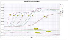
Stratification in a horizontal tank is a frequent question. Attached is a chart which shows charging stratification performance in my 1000 gal pressurized LP storage tank. The chart shows that stratification is quite dramatic. This is a static charge, that is, no hot water was drawn from the tank during the charging process.

The tank is installed in my shop and is insulated to about R-30 (6"+ of fiberglass plus 2" of foam). Hot water supply is 1-1/4" supply line to a 2" horizontal inlet placed on the left end of the tank and 6" down from the top. Cold water return is from a 2" horizontal outlet to 1-1/4" return line placed on the left end of the tank and 6" up from the bottom. The tank is 36" diameter and 19' long.

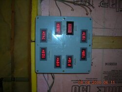
Eight DS19B20 sensors are fixed to the exterior of the tank, 4 on each end and placed on the top, 9" down from the top, 18" down from the top, 27" down from the top, and on the bottom. The sensors are fixed with aluminum tape to the metal tank and fully covered with the tank insulation.

L1 = top sensor on the left end of the tank; R1 - top sensor on the right end of the tank; etc. Also shown are inside, outside and floor temperatures.

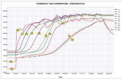
I did not bring the tank up to the maximum possible charge (190F top to bottom), although I have done that it in the past. First boiler fueling was at 12:43 hours and the last boiler fueling was at 18:00 hours. I burned a total of 148 pounds of wood, dry pine/aspen mix. I added wood every 60-90 minutes to maintain a high burn; the Tarm did not idle at any time during the charging process; the circulator is a Grundfos 15-58 on Low speed. Boiler return water protection was maintained between 140-155F. Stack temperature ranged between approximately 375-450F.

There appears to be about a 15-30 minute lag between the time that the temperature begins to rise on the left end of the tank (supply/return side) and the time the temperature begins to rise on the right end of the tank 19' away. But all in all, it appears that very little mixing occurs in the charging process.

Your comments and evaluation are appreciated.
 

Attachments

  • DATAOUT-WEB.jpg
    DATAOUT-WEB.jpg
    30.6 KB · Views: 1,263
Nice curves! Your text says 5 sensors but you only plot 4. I have 2x500 stacked and hope to get them instrumented in October before I fire. I am also going to add a flow meter in the return line which will let me calculate how many BTUs are actually delivered to the tank. Got to get the 1-wire ordered this week.
 
Thank you for the curve compliment.
Your text says 5 sensors but you only plot 4.
I think the text says 8 sensors plus outside, inside, and floor; and the curves show all eleven on my screen.

I still will be adding sensors on both sides of the plate HX and on the mixing valve for the floor radiant to better understand how that actually is operating. Also, that info can be compared to the indoor, outdoor and floor temp sensors to optimize the mixing valve settings for various outdoor temp conditions. With that info, if I want or need to add outdoor reset control, I will have the info to do that.

I had a flowmeter on my prior system but did not install it on this system, mainly because I have only one zone, radiant floor for the shop. The best uses I found for the flowmeter were 1) just as you say, you can actually compute BTU output, 2) you can learn a lot about how your system operates and thereby tune system operation to achieve a more consistent and efficient operation, 3) with sensor info you can see how output varies over a burn cycle and thereby more accurately both load and time the loads for burns which best meet your needs, 4) confirm the benefits of storage by better managing output to system temp and boiler return temp, and probably most "important" 5) satisfy yourself that your boiler can really (or not) put out the advertised BTU's. For example, I now know my Tarm Solo 140 can put out the advertised 140,000 BTU's and also can exceed that during the high burn stage, and that "average" output over a typical load-burn to low coals-reload cycle is in the range of about 70% of rated output.
 
Very nice. It will be interesting if it has a 15 to 30 lag from side to side when you are only pulling the heat. This should inspire others to put in allot of sensors on their tank installs. I can't easily get to mine anymore but the data is pretty cool.
 
When it gets colder so that pulling heat from the tank is more regular, I will do a similar chart starting with the tank fully charged and the boiler "off.". As currently plumbed, I expect the results might be different because I draw from the top at a point about 6' in from the left side, and the return to the tank is via a diptube to the bottom of the tank at about the same point. But the data will tell the story.
 
Some clarifications. At the 130F temperature point:
1) there is a 50 minute lag for R1 to reach the L1 130F temperature (at the same time point, L1 has risen to about 155F)
2) there is a 65 minute lag for R2 to reach the L2 130F temperature (at the same time point, L2 has risen to about 165F)
3) there is a 30 minute lag for R3 to reach the L3 130F temperatures (at the same time point, L3 has risen to about 145F)
4) there is a 10 minute lag for R4 to reach the L4 130F temperatures (at the same time point, L4 has risen to about 135F).

Three things that are very important are that 1) the tank charges high temperature water to the top very well, and the top 2/3 of the tank during the charging maintains a large temperature differential from the bottom 1/3 of the tank; 2) low return temperature water from the bottom 1/3 of the tank maximizes boiler BTUH output and minimizes idling possibilities due to the large delta-T; and, 3) because the tank is a cylinder, the great bulk of the water, and thus the stored BTU's, are in the top 2/3 of the tank.

My calculator shows that the top 1/3 and bottom 1/3 each contain 293 gallons, leaving the middle 1/3 with 414 gallons. Therefore, 70% of the tank volume (700 gallons) is in the top 2/3 of the tank.
 
Gotta say Jim, your test runs provide more fun than anything else on this forum when it comes to interpreting graphs and what they mean about your system. And pressurized storage in general. But maybe I'm prejudiced because I have the same boiler as you.

I believe that if this were a perfect system the graph traces for the two sensors at each height would lay on top of each other and be vertical if the stratification of different water temps were absolute and the thermocline were perfectly level. I doubt anything in a well funded lab would ever even approach that.

I see the time lag between sensors on left and right at the same height as an approximation of the slope of the thermocline (how far off from horizontal), with a little mixing thrown in.

The way the L4 and R4 traces are almost joined shows that the thermocline has become nearly horizontal. Should lay to rest peoples worries about horizontal tanks not being able to stratify well enough for heat storage usage. Here you have what... 5 times wider than tall?

The traces after L1 rise less sharply from the flat beginning temp. I think this displays the inevitable layer of mixed temp water.

Those are my first impressions, anyway. On a really good day I sometimes see half of what's happening in graphs like this. Be interested in your take and that of others around here.

If you decide to take a poll on where to put your next sensors, I would like to be first and request sensors on the supply and return lines to the tank.
 
... and request sensors on the supply and return lines to the tank.

I easily can do that and log those sensors along with the tank sensors. I already have a sensor on boiler supply to the tank but did not log the temp. My "boiler return" sensor actually is a sensor on the bottom of the tank in about the middle of the tank, but it will be easy to have an actual tank to boiler return line sensor. Perhaps the next chart will duplicate this one and add the tank supply and return sensors, and if its is cold enough I can immediately follow it up with the discharge chart.

I too am interested in different takes on this data. I'm open to more suggestions, including additional sensors, although it no longer is very feasible to add more tank sensors because the tank is boxed in. I'm glad I put in the sensors I have when it was easy to do that.
 
Here is another perspective. The chart provides a basis to calculate BTU's from burned wood being transferred to storage, perhaps an "efficiency" measure of performance. A first attempt at a calculation: all temps are approximate --

1) L1/R1 - L2/R2 start temp = 92F; at 21:03 = 182F. BTU's stored = (182-92) x 293 x 8.34 = 220,000

2) L2/R2 - L3/R3 start temp = 92F; at 21:03 = 182F. BTU's stored = (182-92) x 400 x 8.34 = 300,000

3) L3/R3 - L4/R4 start temp = 87F; at 21:03 = 170F. BTU's stored = (170-87) x 293 x 8.34 = 203,000

Stored BTU total = 723,000

148 lbs wood burned (weighed on a bathroom scale): 4,885 BTU/lb delivered to storage; at "assumed" 80% efficiency, gross BTU/lb = 6,100. One of the charts I have shows seasoned jack pine, the primary wood I burned, at 6400 BTU/lb. It looks like there is some reliability in this calculation.
 
Great data. Keep in mind that with the sensors placed on the outside of the steel tank you will see some "smoothing" of the data and some lag on the temps. Bottom line, this is a great set of data. I hope I can do as well! I am looking at ordering 1-wire parts from http://www.hobby-boards.com . They seem to have a good selection and prices. Any other suggestions? I am going to start with the 1-Wire USB adaptor, 6 channel hub, DS18S20 temp sensors, and 20x4 LCD backlight display with controller (for the boiler shed), programmed in Java. I will initially have 2 zones - boiler shed (outside air temp, inside air temp, boiler in, boiler out, and remote LCD display) and mechanical (tanks temps, boiler supply, boiler return, flow meter-later, radiant supply, radiant return), basement temp, main floor temp, second floor temp). What are you using?
 
Good observation and no doubt on the smoothing and lags. I think that I got, though, was I was looking for: good data to show effective stratification in a horizontal tank. I now am interested in collecting data to show the draw down scenario, as well as the scenario for simultaneous charging and draw down. Since this will be the first winter with my new shop, I also am interested in determining actual heat loss compared to calculated heat loss, and also learning an efficient level to which I should charge the tank to achieve desired draw down times between boiler firings. Although my new shop is twice the size of the old poorly insulated shop, my gut tells me that I will be using less wood to heat the new vs the old. Come spring I will know a lot more.

My monitor and control system is very simple and inexpensive. A Johnson A419 controls the radiant in-floor. A Honeywell 2-stage T775A controls the boiler. Also 8 digital panel meters solely for monitoring, 7 using DS18B20's (boiler supply, boiler return, radiant supply, radiant return, top of tank, middle of tank, bottom of tank) and one using K-type probe for stack temp. All controls, panel meters, and D18B20's were bought off of ebay. I now also am using the 1-wire adapter from PCsensor with DS18B20's for data logging and simple charting, and I read the logged data into my database program for any desired selection, analysis and comparison, along with data output for my stand-alone charting program. I will be adding more DS18B20's for additional data logging through the 1-wire adapter.
 

Attachments

  • DSCN1706.jpg
    DSCN1706.jpg
    37.8 KB · Views: 881
At DaveBP's suggestion, I added supply and return sensors. The additional data proved to be helpful.

I shut the boiler off at 19:28; that's where the SU and RT lines fall off rapidly on the right side of the chart.

1) Return rises much faster than bottom of tank (L4/R4) but does lag L3/R3. L3/R3 are 12" up from the bottom, the bottom of tank sensors L4/R4 are on the very bottom of the tank, and the return outlet from the tank is 6" from the bottom. This would indicate that water temp 6" and up from the bottom is highly stratified from the tank bottom and is heated little, if any, by mixing from above. My calculator shows that the bottom 6" of the 1000 gal tank holds 100 gallons of water.

2) The lack of mixing at the bottom gives reason to believe that there isn't much mixing occurring at above levels either. I suspect that due to the length of the tank there is "rolling" wave of hot water from left to right which is quite stratified from cooler water below. The lags between L1/R1 etc. reflect the rolling wave of hot water. Also, when sensors on the same end of the tank are compared with sensors above and below at the same time, there is a large temperature differential. For example if L1 (top of tank) and L2 (down 12" from top) are compared at time 12:20, L1=164 and L2=135. Similarly, at time 13:05 R1=176 and R2=138. This same type of comparison can be made at other times with similar results.

3) The last 100 gallons of water does eventually heat, but it appears that it heats mostly by radiation and/or convection from the hot water lying above and the tank itself rather than from hot water being supplied by the boiler. I think that in a perfectly insulated tank, over time the entire tank would stabilize at the same temperature. This tank charge stabilized (from the underlying data) at 19:45 -- L1-193, R1-192, L2-193, R2-191, L3-192, R-3-193, L4-184, and R4-186.

4) I initially thought that by not having the return at the very bottom of the tank and being able to directly heat that last 100 gallons of water I might be losing some significant heat storage capacity. But based on where the tank stabilized, I calculate that I am losing only about 3% or less of the tank storage heating capacity. Calculations are based on the top 700 gallons at 192 and the bottom 293 gallons at 185, with minimum usable water temp of 100 (radiant in-floor heat).

4) At 15:20 (and SU peaks thereafter) the boiler went into idle periods. RT at that time was 170 and rising. I then turned the speed of the 15-58 to HI, but I no longer could move sufficient water to prevent additional idling. The last wood was loaded at 14:30, and before that time I loaded wood regularly to maintain high burn. Stack temps were in the 350-450 range throughout the burn.

5) The SU trough at 14:30 and before roughly indicate when wood was loaded into the boiler. So after the initial loading I only loaded 3 additional times. All wood was dry jack pine this time.

Once again, additional observations and questions are appreciated.
 

Attachments

  • DATOUT-WEB.jpg
    DATOUT-WEB.jpg
    45.8 KB · Views: 776
Here is the chart for static stratification after charging from 10/01 to 10/06. This chart continues the prior chart. Both excellent stratification and pretty good tank insulation are evidenced. I suppose if insulation was perfect, tank temp would be the same top to bottom. I do have some ghost flow through the supply and return lines, which are short and insulated. I did not put check valves or heat traps on these because I thought heat loss would be quite low and any heat loss only goes to heat the shop anyway.

The spike on 10/02 occurred when I accidentally ran the tank circulator, resulting in mixing of the tank at that point.

Starting data values on 10/01 at 7:18 PM:
L1/R1 194/192
L2/R2 193/191
L3/R3 192/194
L4/R4 182/182

Values at mixing on 10/02 at 1:41 PM:

L1/R1 183/181
L2/R2 182/180
L3/R3 181/183
L4/R4 178/181

Ending values on 10/06 at 5:46 AM:

L1/R1 149/149
L2/R2 146/147
L3/R3 146/140
L4/R4 134/135

The values this morning on 10/12 at 5:30 AM:

L1/R1 117/116
L2/R2 115/115
L3/R3 112/111
L4/R4 107/107
 

Attachments

  • DATAOUT3-WEB.jpg
    DATAOUT3-WEB.jpg
    31.6 KB · Views: 647
The data and chart allow a heat calculation to be made for the period from 10/01 - 10/06. Average tank temperature at 7:18 PM on 10/01 was about 190, and stored BTU's were 1,584,600. Average tank temperature at 5:46 AM on 10/06 was about 144, and stored BTU's were 1,200,960. Total BTU's used for the 4.5 day period were 383,640, or 85,250 BTU/day, or 3,550 BTUH. Interior shop temperature was about 70-72.
 
jebatty = data junkie... ;-)
Seriously though great thread, I learn a bunch from these posts. I have my variable speed boiler and bypass loops set up
and under the control of the nfcs and when I get a chance I will post some graphs with my open storage. I am probably going to
switch to pressurized storage and I think my setup will work great with a pair of 500 gallon tanks (can't fit a 1000 gallon).

Keep the data coming...

Kris
 
Status
Not open for further replies.